- 您现在的位置:买卖IC网 > PDF目录98179 > TC7135CBURT 1-CH DUAL-SLOPE ADC, ACCESS, PQFP64 PDF资料下载
参数资料
| 型号: | TC7135CBURT |
| 元件分类: | ADC |
| 英文描述: | 1-CH DUAL-SLOPE ADC, ACCESS, PQFP64 |
| 封装: | PLASTIC, QFP-64 |
| 文件页数: | 1/16页 |
| 文件大小: | 217K |
| 代理商: | TC7135CBURT |
TC7135
TC7135-10 9/27/99
TelCom Semiconductor reserves the right to make changes in the circuitry and specifications of its devices.
GENERAL DESCRIPTION
The TC7135 4-1/2 digit analog-to-digital converter (ADC)
offers 50 ppm (1 part in 20,000) resolution with a maximum
nonlinearity error of 1 count. An auto-zero cycle reduces zero
error to below 10
V and zero drift to 0.5V/°C. Source
impedance errors are minimized by a 10pA maximum input
current. Roll-over error is limited to
±1 count.
By combining the TC7135 with a TC7211A (LCD) driver,
a 4-1/2 digit display DVM or DPM can be constructed.
Overrange and underrange signals support automatic range
switching and special display blanking/flashing applications.
Microprocessor-based measurement systems are sup-
ported by BUSY, STROBE, and RUN/HOLD control signals.
Remote data acquisition systems with data transfer via UARTs
are also possible. The additional control pins and multiplexed
BCD outputs make the TC7135 the ideal converter for dis-
play or microprocessor-based measurement systems.
ORDERING INFORMATION
Temperature
Part No.
Package
Range
TC7135CBU
64-Pin PQFP
0
°C to +70°C
TC7135CLI
28-Pin PLCC
0
°C to +70°C
TC7135CPI
28-Pin PDIP
0
°C to +70°C
TC7135
–5V
V
REF IN
ANALOG
COMMON
UR
OR
STROBE
RUN/HOLD
DGND
POL
CLOCK
BUSY
D1
D2
D3
0.1F
0.47F
1F
ANALOG
GROUND
100k
0.1
F
INPUT
1
2
3
4
5
6
7
8
9
10
11
12
13
14
+5V
28
27
26
25
24
23
22
21
20
19
TC04
+5V
1/4 CD4030
CLOCK IN
+5V
BP
D
1
2
3
4
4-1/2 DIGIT LCD
SEGMENT
D
R
I
V
E
5
31
32
33
34
30
29
28
27
TC7211A
SEG
OUT
OSC
GND
36
+5V
1
CD4081
1 1615 1412 5 3 4
7 8 13 11 10 9 2 6
CD4054A
OPTIONAL
CAP
35
15
120Hz = 3 READING/SEC
BACKPLANE
B
3
2
1
0
D4
B8
B4
18
17
16
100k
100k
6.8k
1F
INT OUT
AZ IN
BUFF OUT
CREF
–INPUT
+INPUT
V
D5
B1
B2
+
V
+
2,3,4
6–26
37–40
+
–
+5V
FEATURES
s
Low Roll-Over Error ..........................
±1 Count Max
s
Guaranteed Nonlinearity Error .........
±1 Count Max
s
Guaranteed Zero Reading for 0V Input
s
True Polarity Indication at Zero for Null Detection
s
Multiplexed BCD Data Output
s
TTL-Compatible Outputs
s
Differential Input
s
Control Signals Permit Interface to UARTs and
Processors
s
Auto-Ranging Supported With Overrange and
Underrange Signals
s
Blinking Display Visually Indicates Overrange
Condition
s
Low Input Current .............................................. 1pA
s
Low Zero Reading Drift ................................ 2
V/°C
s
Available in DIP and Surface-Mount Packages
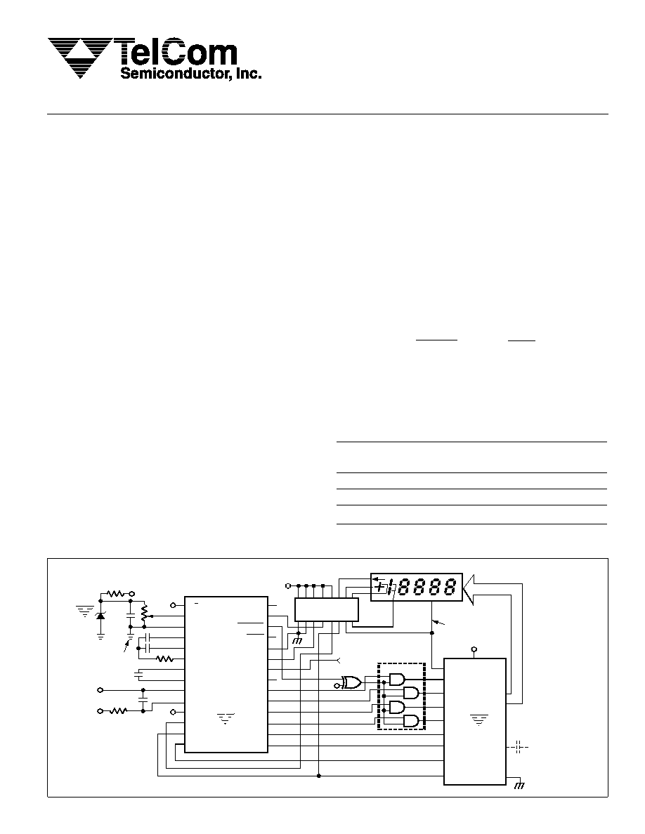
TYPICAL 4-1/2 DIGIT DVM WITH LCD
4-1/2 DIGIT ANALOG-TO-DIGITAL CONVERTER
相关PDF资料 |
PDF描述 |
|---|---|
| TC7135CLI | 1-CH DUAL-SLOPE ADC, PQCC28 |
| TC7135CBUTR | 1-CH DUAL-SLOPE ADC, PQFP64 |
| TC7135CKW | 1-CH DUAL-SLOPE ADC, PQFP64 |
| TC7135CLITR | 1-CH DUAL-SLOPE ADC, PQCC28 |
| TC7135CPI | 1-CH DUAL-SLOPE ADC, PDIP28 |
相关代理商/技术参数 |
参数描述 |
|---|---|
| TC7135CKW | 制造商:MICROCHIP 制造商全称:Microchip Technology 功能描述:4-1/2 Digit A/D Converter |
| TC7135CLI | 功能描述:LED显示驱动器 4-1/2 Digit A/D BCD RoHS:否 制造商:Micrel 数位数量:5 片段数量: 安装风格:SMD/SMT 封装 / 箱体:PLCC-44 工作电源电压:4.75 V to 11 V 最大电源电流:10 mA 最大工作温度:+ 85 C 最小工作温度:- 40 C 封装:Tube |
| TC7135CLI713 | 功能描述:LED显示驱动器 4-1/2 Digit A/D BCD RoHS:否 制造商:Micrel 数位数量:5 片段数量: 安装风格:SMD/SMT 封装 / 箱体:PLCC-44 工作电源电压:4.75 V to 11 V 最大电源电流:10 mA 最大工作温度:+ 85 C 最小工作温度:- 40 C 封装:Tube |
| TC7135CPI | 功能描述:LED显示驱动器 4-1/2 Digit A/D BCD RoHS:否 制造商:Micrel 数位数量:5 片段数量: 安装风格:SMD/SMT 封装 / 箱体:PLCC-44 工作电源电压:4.75 V to 11 V 最大电源电流:10 mA 最大工作温度:+ 85 C 最小工作温度:- 40 C 封装:Tube |
| TC7135CPL | 制造商:MICROCHIP 制造商全称:Microchip Technology 功能描述:4-1/2 Digit A/D Converter |
发布紧急采购,3分钟左右您将得到回复。