- 您现在的位置:买卖IC网 > PDF目录98187 > TCT150A 1 FUNCTIONS, 100 V, 10 A, FEED THROUGH CAPACITOR PDF资料下载
参数资料
| 型号: | TCT150A |
| 元件分类: | 数据传输滤波器 |
| 英文描述: | 1 FUNCTIONS, 100 V, 10 A, FEED THROUGH CAPACITOR |
| 文件页数: | 16/16页 |
| 文件大小: | 328K |
| 代理商: | TCT150A |
Miniature Threaded
28 OxleyDevelopmentsCompanyLtd
Email: sales@oxley.co.uk
Tel: +44 (0)1229 840607
Oxley Group Australia Pty Ltd
Email: sales@oxleygroup.com
Tel +61 (0) 2 9967 9488
Oxley Inc.
Email: sales@oxleyinc.com
Tel: +1 (203) 488 1033
www.oxleygroup.com/emc
ODCSM40489/4/2005
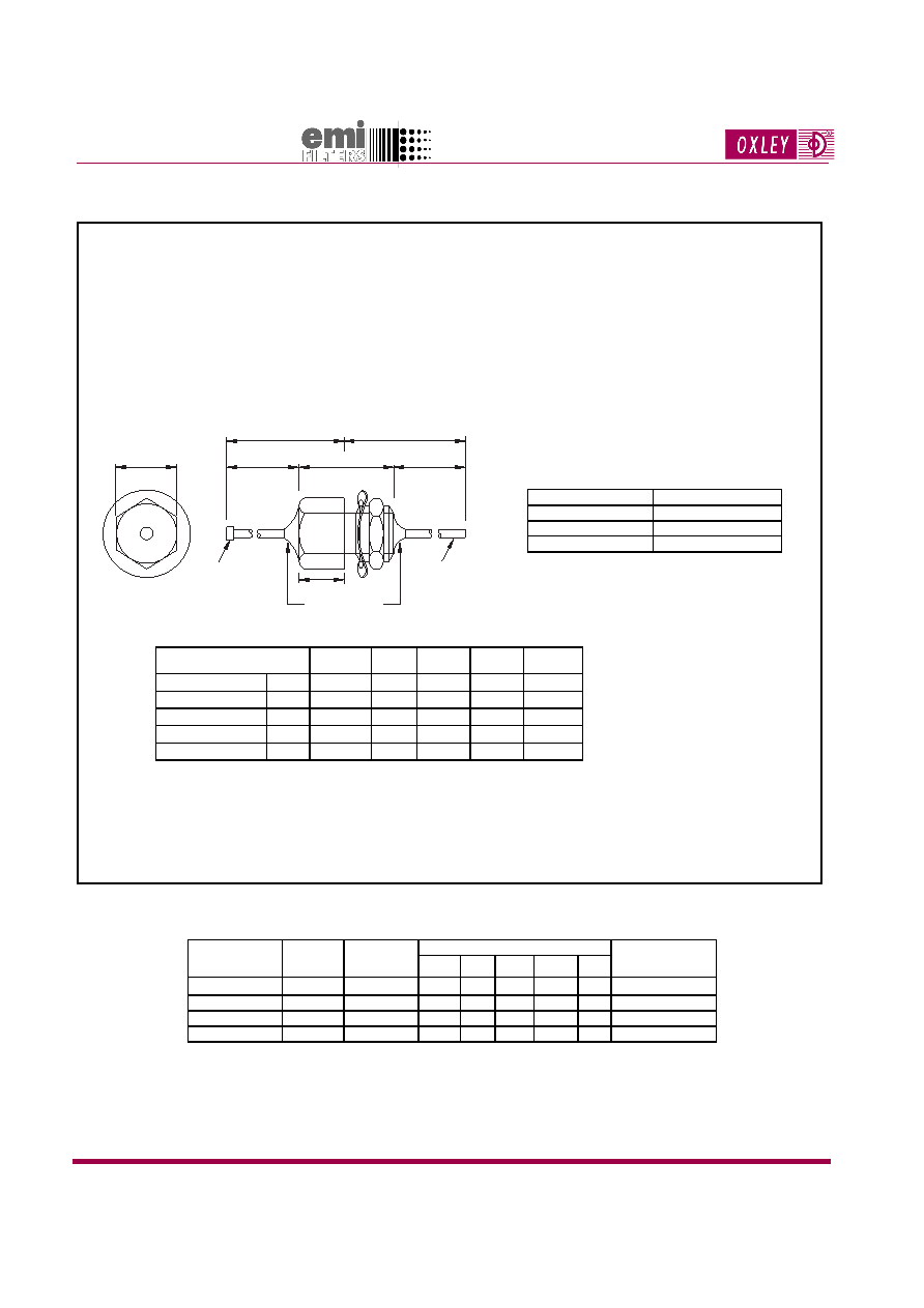
Miniature Threaded TVS Circuit Filters
DLT/-/TVS
Characteristics
1 Insert nominal working voltage in V (5, 14 or 18).
2 Value coding may replace color code.
Part Number
Nominal
capacitance
(pF)
Current Rating
(A d.c. 400 Hz)
Typical Insertion Loss (dB) (50
system)
Color Code2
(hex end/thread end)
0.1 MHz 1 Mhz 10 MHz 100 MHz 1 GHz
DLT/4700/-1/TVS
4700
10
-
3
20
38
53
RED/WHITE
DLT/10000/-/TVS
10000
10
1
8
27
44
63
BLUE/WHITE
DLT/47000/-/TVS
47000
10
4
20
41
45
74
LIGHT BLUE/WHITE
DLT/100000/-/TVS
100000
10
2
25
45
57
75
LIGHT BROWN/WHITE
Marking: In addition to color code, a transient protected device is indicated by a black or
white dot on the color coding to distinguish it from the standard DLT/- range.
6.4 A/F
13.4 max.
6.4
5 max.
11.5 max.
6.4
19.8 max.
0.7
Color Coding
1 x 0.5
Ordering Information
Please state Part Number and quantity. Remember to include the
working voltage in the Part Number.
Supplied without nut as standard.
Materials
Body: Brass, tin finish.
Feedthrough terminations: Copper alloy, tin lead or silver finish.
Case Dimensions
All dimensions in millimetres.
Mounting Details
Thread
2 BA
Chassis Thickness (max.)
1.2 - 1.6 mm
Minimum Pitch
8mm
Mounting Torque
0.35 Nm
Transient Voltage Performance
Parameter
Test
Conditions
-/5/TVS
-/14/TVS
-/18/TVS
Unit
Working Voltage (d.c.)
VWM
<50A
5.6
14
18
Volt (max.)
Breakdown Voltage
VB
1 mA d.c.
7.1 - 8.7 15.9 - 19.4 22.5 - 27.5
Volt (max.)
Clamping Voltage
VC
10 A 8/20 s
15.5
30
40
Volt (max.)
Peak Current
Ipeak
8/20 s
120
100
Amp (max.)
Transient Energy
Etran
10/1000 s
0.3
Joule (max.)
VWM - Maximum steady-state d.c. operating voltage the device can maintain and not exceed 50 A leakage current.
VB
- Voltage across the device measured at 1 mA d.c. current.
VC
- Maximum peak voltage across the device measured at a specified pulse current and waveform.
Ipeak - Maximum peak current which may be applied with the specified waveform without device failure.
Etran - Maximum energy which may be dissipated with the specified waveform without device failure.
相关PDF资料 |
PDF描述 |
|---|---|
| TCT150B | 1 FUNCTIONS, 100 V, FEED THROUGH CAPACITOR |
| TCT101C | 1 FUNCTIONS, 300 V, 10 A, FEED THROUGH CAPACITOR |
| TCT101D | 1 FUNCTIONS, 300 V, FEED THROUGH CAPACITOR |
| TCT101E | 1 FUNCTIONS, 300 V, 10 A, FEED THROUGH CAPACITOR |
| TCT101F | 1 FUNCTIONS, 300 V, FEED THROUGH CAPACITOR |
相关代理商/技术参数 |
参数描述 |
|---|---|
| TCT-15PO | 功能描述:打印机 LS6 Continuous Tape Polyolefin 0.38" RoHS:否 制造商:Seiko Instruments 产品:Printer 电源电压: 每行点数:9 x 320 打印速度:52.5 cps, 80 cps 纸张宽度:112 mm |
| TCT-16V | 制造商:Panduit Corp 功能描述: |
| TCT-17V | 制造商:Panduit Corp 功能描述:LS6 2" X 50' RED - Tape and Reel |
| TCT-1V | 功能描述:打印机 LS6 CONT TAPE, 1.00" X 50’, VINYL, WHT RoHS:否 制造商:Seiko Instruments 产品:Printer 电源电压: 每行点数:9 x 320 打印速度:52.5 cps, 80 cps 纸张宽度:112 mm |
| TCT2 | 制造商:Hubbell Premise Wiring 功能描述: 制造商:Hubbell Wiring Device-Kellems 功能描述:TESTER, CONTINUITY,UTP/COAX,2 ADAP |
发布紧急采购,3分钟左右您将得到回复。