- 您现在的位置:买卖IC网 > PDF目录299960 > TD1N5222D 2.5 V, 0.5 W, SILICON, UNIDIRECTIONAL VOLTAGE REGULATOR DIODE, DO-35 PDF资料下载
参数资料
| 型号: | TD1N5222D |
| 元件分类: | 参考电压二极管 |
| 英文描述: | 2.5 V, 0.5 W, SILICON, UNIDIRECTIONAL VOLTAGE REGULATOR DIODE, DO-35 |
| 封装: | HERMETIC SEALED, GLASS PACKAGE-2 |
| 文件页数: | 2/7页 |
| 文件大小: | 181K |
| 代理商: | TD1N5222D |
June 2004 / C
Page 2
SEMICONDUCTOR
TAK CHEONG
Electrical Characteristics
TA = 25°C unless otherwise noted
Device Type
VZ @ IZT
(Volts)
Nominal
IZT
(mA)
ZZT @ IZT
(
)
Max
ZZK @ IZK = 0.25mA
(
)
Max
IR @ VR
(
A)
Max
VR
(Volts)
TC1N5245B
15
8.5
16
600
0.1
11
TC1N5246B
16
7.8
17
600
0.1
12
TC1N5247B
17
7.4
19
600
0.1
13
TC1N5248B
18
7
21
600
0.1
14
TC1N5249B
19
6.6
23
600
0.1
14
TC1N5250B
20
6.2
25
600
0.1
15
TC1N5251B
22
5.6
29
600
0.1
17
TC1N5252B
24
5.2
33
600
0.1
18
TC1N5253B
25
5
35
600
0.1
19
TC1N5254B
27
4.6
41
600
0.1
21
TC1N5255B
28
4.5
44
600
0.1
21
TC1N5256B
30
4.2
49
600
0.1
23
TC1N5257B
33
3.8
58
700
0.1
25
TC1N5258B
36
3.4
70
700
0.1
27
TC1N5259B
39
3.2
80
800
0.1
30
TC1N5258B
36
3.4
70
700
0.1
27
TC1N5259B
39
3.2
80
800
0.1
30
TC1N5260B
43
3
93
900
0.1
33
TC1N5261B
47
2.7
105
1000
0.1
36
TC1N5262B
51
2.5
125
1100
0.1
39
TC1N5263B
56
2.2
150
1300
0.1
43
VF Forward Voltage = 1.1 V Maximum @ IF = 200 mA for all types
Notes:
1.
The type numbers listed have zener voltage as shown and have a standard tolerance on the nominal zener voltage of ±5%.
Suffix A = ±10%, C = ±2% and D = ±1%.
2.
For detailed information on price, availability and delivery of nominal zener voltages between the voltages shown and tighter
voltage tolerances, contact your nearest Tak Cheong Electronics representative.
3.
The zener impedance is derived from the 60-cycle ac voltage, which results when an ac current having an rms value equal to
10% of the dc zener current (IZT or IZK) is superimposed to IZT or IZK.
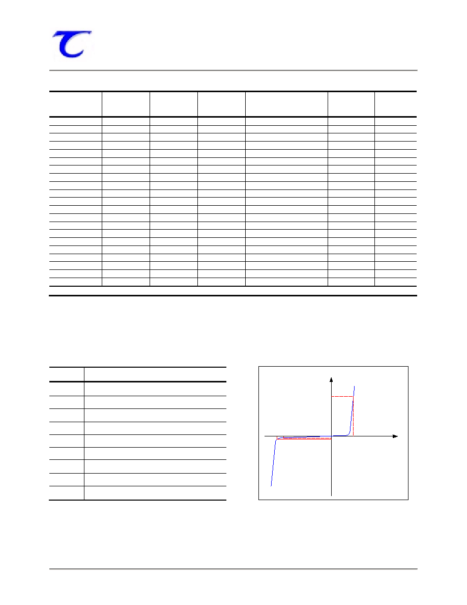
Electrical Symbol Definition
Typical Characteristics
Symbol
Parameter
VZ
Reverse Zener Voltage @ IZT
IZT
Reverse Current
ZZT
Maximum Zener Impedance @ IZT
IZK
Reverse Current
ZZK
Maximum Zener Impedance @ IZK
IR
Reverse Leakage Current @ VR
VR
Breakdown Voltage
IF
Forward Current
VF
Forward Voltage @ IF
V
I
(mV)
(V)
(mA)
VF
IF
VR
IR
VZ
IZT
(nA)
相关PDF资料 |
PDF描述 |
|---|---|
| TD1N5242D | 12 V, 0.5 W, SILICON, UNIDIRECTIONAL VOLTAGE REGULATOR DIODE, DO-35 |
| TD430N18KOC | 800 A, 1800 V, SCR |
| TD430N20KOC | 800 A, 2000 V, SCR |
| TD430N22KOC | 800 A, 2200 V, SCR |
| TD8086 | 16-BIT, 5 MHz, MICROPROCESSOR, CDIP40 |
相关代理商/技术参数 |
参数描述 |
|---|---|
| TD2 | 制造商:Middle Atlantic Products 功能描述: |
| TD2.2M10 | 制造商:NTE Electronics 功能描述: |
| TD2.2M16 | 制造商:NTE Electronics 功能描述: |
| TD2.2M20 | 制造商:NTE 制造商全称:NTE Electronics 功能描述:SOLID TANTALUM |
| TD2.2M25 | 制造商:NTE 制造商全称:NTE Electronics 功能描述:SOLID TANTALUM |
发布紧急采购,3分钟左右您将得到回复。