- 您现在的位置:买卖IC网 > PDF目录98190 > TDA2052V (STMICROELECTRONICS) 60 W, 1 CHANNEL, AUDIO AMPLIFIER, PZFM7 PDF资料下载
参数资料
| 型号: | TDA2052V |
| 厂商: | STMICROELECTRONICS |
| 元件分类: | 音频/视频放大 |
| 英文描述: | 60 W, 1 CHANNEL, AUDIO AMPLIFIER, PZFM7 |
| 封装: | HEPTAWATTV-7 |
| 文件页数: | 8/14页 |
| 文件大小: | 4114K |
| 代理商: | TDA2052V |
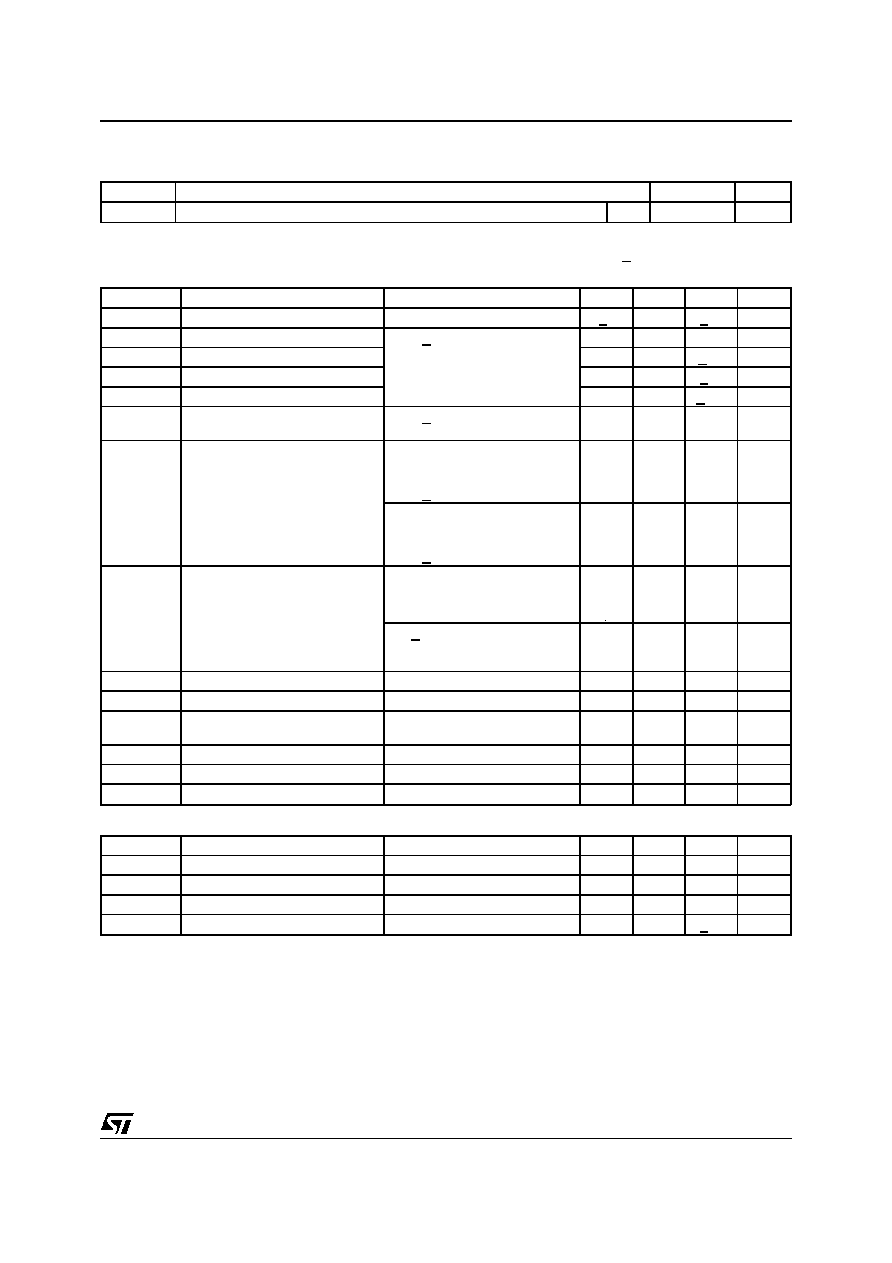
ELECTRICAL CHARACTERISTICS (Refer to the test circuit, GV = 32dB; VS + 18V; f = 1KHz; Tamb =
25
°C, unless otherwise specified.)
Symbol
Parameter
Test Condition
Min.
Typ.
Max.
Unit
VS
Supply Range
+6
+25
V
Iq
Total Quiescent Current
VS = +22V
20
40
70
mA
Ib
Input Bias Current
+0.5
A
VOS
Input Offset Voltage
+15
mV
IOS
Input Offset Current
+200
nA
PO
Music Output Power
IEC268-3 Rules (*)
VS = + 22.5, RL = 4
,
d = 10%, t = 1s
50
60
W
PO
Output Power (continuous RMS)
d = 10%
RL = 4
RL = 8
VS = +22V, RL = 8
35
30
40
22
33
W
d = 1%
RL = 4
RL = 8
VS = +22V, RL = 8
32
17
28
W
d
Total Harmonic Distortion
RL = 4
PO = 0.1 to 20W;
f = 100Hz to 15KHz
VS + 22V, RL = 8
PO = 0.1 to 20W;
f = 100Hz to 15KHz
0.1
0.7
0.5
%
SR
Slew Rate
3
5
V/
s
GV
Open Loop Voltage Gain
80
dB
eN
Total Input Noise
A Curve
f = 20Hz to 20KHz
2
310
V
Ri
Input Resistance
500
K
SVR
Supply Voltage Rejection
f = 100Hz, Vripple = 1VRMS
40
50
dB
TS
Thermal Shutdown
145
°C
MUTE/STAND-BY FUNCTION (Ref. –VS)
VTST-BY
Stand-by - Threshold
1
1.8
V
VTPLAY
Play Threshold
2.7
4
V
Iq ST-BY
Quiescent Current @ Stand-by
Vpin 3 = 0.5V
1
3
mA
ATTST-BY
Stand-by Attenuation
70
90
dB
Ipin3
Pin 3 Current @ Stand-by
–1
+10
A
Note (*):
MUSIC POWER CONCEPT
MUSIC POWER is ( according to the IEC clauses n.268-3 of Jan 83) the maximal power which the amplifier is capable of producing across the
rated load resistance (regardless of non linearity) 1 sec after the application of a sinusoidal input signal of frequency 1KHz.
According to this definition our method of measurement comprises the following steps:
1) Set the voltage supply at the maximum operating value -10%
2) Apply a input signal in the form of a 1KHz tone burst of 1 sec duration; the repetition period of the signal pulses is > 60 sec
3) The output voltage is measured 1 sec from the start of the pulse
4) Increase the input voltage until the output signal show a THD = 10%
5) The music power is then V
2
out/R1, where Vout is the output voltage measured in the condition of point 4) and R1 is the rated load impedance
The target of this method is to avoid excessive dissipation in the amplifier.
THERMAL DATA
Symbol
Description
Value
Unit
Rth j-case
Thermal Resistance Junction-case
Max
2.5
°C/W
TDA2052
3/14
相关PDF资料 |
PDF描述 |
|---|---|
| TDA2052 | 60 W, 1 CHANNEL, AUDIO AMPLIFIER, PSFM7 |
| TDA2320A | 2 CHANNEL, AUDIO AMPLIFIER, PDIP8 |
| TDA2577AN | HORIZ/VERT DEFLECTION IC, PDIP18 |
| TDA2578A | HORIZ/VERT DEFLECTION IC, PDIP18 |
| TDA2579CN | HORIZ/VERT DEFLECTION IC, PDIP18 |
相关代理商/技术参数 |
参数描述 |
|---|---|
| TDA2054M | 制造商:STMICROELECTRONICS 制造商全称:STMicroelectronics 功能描述:PREAMPLIFIER WITH ALC FOR CrO2 CASSETTE RECODERS |
| TDA2075A | 制造商:TRIPATH 制造商全称:TRIPATH 功能描述:STEREO CLASS-T DIGITAL AUDIO AMPLIFIER DRIVER USING DIGITAL POWER PROCESSINGTM TECHNOLOGY |
| TDA2085 | 制造商:未知厂家 制造商全称:未知厂家 功能描述:CLOSED LOOP CONTROL |
| TDA2085A | 制造商:未知厂家 制造商全称:未知厂家 功能描述:CLOSED LOOP CONTROL |
| TDA2088 | 制造商:未知厂家 制造商全称:未知厂家 功能描述:PHASE CONTROL INTEGRATED CURCUIT FOR CURRENT FEEDBACK APPLICATION |
发布紧急采购,3分钟左右您将得到回复。