- 您现在的位置:买卖IC网 > PDF目录98190 > TDA3629T-T (NXP SEMICONDUCTORS) SPECIALTY CONSUMER CIRCUIT, PDSO16 PDF资料下载
参数资料
| 型号: | TDA3629T-T |
| 厂商: | NXP SEMICONDUCTORS |
| 元件分类: | 消费家电 |
| 英文描述: | SPECIALTY CONSUMER CIRCUIT, PDSO16 |
| 文件页数: | 5/28页 |
| 文件大小: | 175K |
| 代理商: | TDA3629T-T |
第1页第2页第3页第4页当前第5页第6页第7页第8页第9页第10页第11页第12页第13页第14页第15页第16页第17页第18页第19页第20页第21页第22页第23页第24页第25页第26页第27页第28页
1996 Sep 04
13
Philips Semiconductors
Product specication
Light position controller
TDA3629
Table 1
Duration of the pauses
The maximum allowable dissipated power P is then
0.77 W during the motor active periods in the event of a
DIP8 package being used. Dissipation pulses due to
starting and stopping the motor can be ignored because of
their short duration. This maximum allowable dissipated
power implies that the maximum continuous motor current
(
I
m) is approximately 250 mA during the motor active
periods when the supply voltage VP is 13 V. The maximum
allowable dissipated power P is 0.67 W during the motor
active periods in the event of a SO16 package being used.
This implies that the maximum continuous motor current
(
I
m) is approximately 220 mA during the motor active
periods when the supply voltage (VP) is 13 V.
Tamb (°C)
PAUSE (s)
<95
60
95
180
95 to 105
300
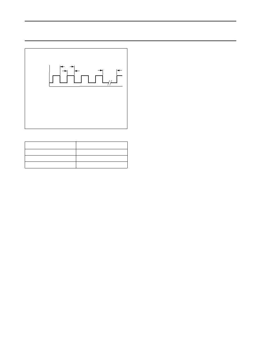
Fig.11 Thermal transient test.
The duration of the pause depends on the ambient temperature, see
Table 1.
handbook, halfpage
MGE642
active
motor
inactive
pause
8 s
4 s
time (s)
Stereo operation
The default application will be when two modules are
driven by one set potentiometer. One module controls the
left head light, where the other one controls the right head
light. Each module is connected by three wires: the battery
line, the ground line and the set input wire. This can result
in two additional fault conditions: from one module the
battery line or the ground line can be broken, when the
other module is still connected. Assume that the left one
operates normally, where the right one has a fault. The
setting potentiometer will have extra loading when the
battery line is broken. This will result in a lower voltage at
the wiper of the setting potentiometer. Thus the left module
will start to regulate until a new equilibrium is reached.
The amount of extra loading can be influenced by the
external series resistor in the set input. These fault
conditions and their implications should be considered
when the total application is designed.
Test diagram
All parameters in chapter “Characteristics” until this
section are measured at Tamb = 25 °C and are tested at
each device using the test set-up of Fig.12. The only
exceptions are parameters supply current (motor active)
and output voltage (motor output) where the 1 k
output
resistor is replaced by an appropriate current source.
相关PDF资料 |
PDF描述 |
|---|---|
| TDA3842T | AM, VIDEO DISCRIMINATOR, PDSO20 |
| TDA3842T-T | AM, VIDEO DISCRIMINATOR, PDSO20 |
| TDA3842 | AM, VIDEO DISCRIMINATOR, PDIP20 |
| TDA3853T-T | AM, VIDEO DISCRIMINATOR, PDSO20 |
| TDA3856T-T | AM/FM, AUDIO DEMODULATOR, PDSO24 |
相关代理商/技术参数 |
参数描述 |
|---|---|
| TDA3651 | 制造商:PHILIPS 制造商全称:NXP Semiconductors 功能描述:VERTICAL DEFLECTION CIRCUIT |
| TDA3651A | 制造商:PHILIPS 制造商全称:NXP Semiconductors 功能描述:VERTICAL DEFLECTION CIRCUIT |
| TDA3651Q | 制造商:PHILIPS 制造商全称:NXP Semiconductors 功能描述:VERTICAL DEFLECTION CIRCUIT |
| TDA3652 | 制造商:未知厂家 制造商全称:未知厂家 功能描述:TDA2578A SYNC APPLICATION TDA3652 VERTICAL DEFLECTION APPLICATION |
| TDA3653 | 制造商:PHILIPS 制造商全称:NXP Semiconductors 功能描述:VERTICAL DEFLECTION AND GUARD CIRCUIT 90° |
发布紧急采购,3分钟左右您将得到回复。