- 您现在的位置:买卖IC网 > PDF目录17085 > TDGL001 (Microchip Technology)BOARD DEV CEREBOT 32MX4 PDF资料下载
参数资料
| 型号: | TDGL001 |
| 厂商: | Microchip Technology |
| 文件页数: | 142/214页 |
| 文件大小: | 0K |
| 描述: | BOARD DEV CEREBOT 32MX4 |
| 标准包装: | 1 |
| 系列: | PIC® 32MX |
| 类型: | MCU |
| 适用于相关产品: | PIC32MX460F512 |
| 所含物品: | 板 |
第1页第2页第3页第4页第5页第6页第7页第8页第9页第10页第11页第12页第13页第14页第15页第16页第17页第18页第19页第20页第21页第22页第23页第24页第25页第26页第27页第28页第29页第30页第31页第32页第33页第34页第35页第36页第37页第38页第39页第40页第41页第42页第43页第44页第45页第46页第47页第48页第49页第50页第51页第52页第53页第54页第55页第56页第57页第58页第59页第60页第61页第62页第63页第64页第65页第66页第67页第68页第69页第70页第71页第72页第73页第74页第75页第76页第77页第78页第79页第80页第81页第82页第83页第84页第85页第86页第87页第88页第89页第90页第91页第92页第93页第94页第95页第96页第97页第98页第99页第100页第101页第102页第103页第104页第105页第106页第107页第108页第109页第110页第111页第112页第113页第114页第115页第116页第117页第118页第119页第120页第121页第122页第123页第124页第125页第126页第127页第128页第129页第130页第131页第132页第133页第134页第135页第136页第137页第138页第139页第140页第141页当前第142页第143页第144页第145页第146页第147页第148页第149页第150页第151页第152页第153页第154页第155页第156页第157页第158页第159页第160页第161页第162页第163页第164页第165页第166页第167页第168页第169页第170页第171页第172页第173页第174页第175页第176页第177页第178页第179页第180页第181页第182页第183页第184页第185页第186页第187页第188页第189页第190页第191页第192页第193页第194页第195页第196页第197页第198页第199页第200页第201页第202页第203页第204页第205页第206页第207页第208页第209页第210页第211页第212页第213页第214页
2011 Microchip Technology Inc.
DS61143H-page 33
PIC32MX3XX/4XX
2.5
ICSP Pins
The PGECx and PGEDx pins are used for In-Circuit
Serial Programming (ICSP) and debugging pur-
poses. It is recommended to keep the trace length
between the ICSP connector and the ICSP pins on the
device as short as possible. If the ICSP connector is
expected to experience an ESD event, a series resistor
is recommended, with the value in the range of a few
tens of Ohms, not to exceed 100 Ohms.
Pull-up resistors, series diodes and capacitors on the
PGECx and PGEDx pins are not recommended as they
will interfere with the programmer/debugger communi-
cations to the device. If such discrete components are
an application requirement, they should be removed
from the circuit during programming and debugging.
Alternately, refer to the AC/DC characteristics and tim-
ing requirements information in the respective device
Flash programming specification for information on
capacitive loading limits and pin input voltage high (VIH)
and input low (VIL) requirements.
Ensure that the “Communication Channel Select” (i.e.,
PGECx/PGEDx pins) programmed into the device
matches the physical connections for the ICSP to
MPLAB ICD 2, MPLAB ICD 3 or MPLAB REAL ICE.
For more information on ICD 2, ICD 3 and REAL ICE
connection
requirements,
refer
to
the
following
documents that are available on the Microchip web
site.
“MPLAB ICD 2 In-Circuit Debugger User’s
Guide” DS51331
“Using MPLAB ICD 2” (poster) DS51265
“MPLAB ICD 2 Design Advisory” DS51566
“Using MPLAB ICD 3” (poster) DS51765
“MPLAB ICD 3 Design Advisory” DS51764
“MPLAB REAL ICE In-Circuit Debugger
User’s Guide” DS51616
“Using MPLAB REAL ICE” (poster) DS51749
2.6
JTAG
The TMS, TDO, TDI and TCK pins are used for testing
and debugging according to the Joint Test Action
Group (JTAG) standard. It is recommended to keep the
trace length between the JTAG connector and the
JTAG pins on the device as short as possible. If the
JTAG connector is expected to experience an ESD
event, a series resistor is recommended, with the value
in the range of a few tens of Ohms, not to exceed 100
Ohms.
Pull-up resistors, series diodes and capacitors on the
TMS, TDO, TDI and TCK pins are not recommended
as they will interfere with the programmer/debugger
communications to the device. If such discrete compo-
nents are an application requirement, they should be
removed from the circuit during programming and
debugging. Alternately, refer to the AC/DC characteris-
tics and timing requirements information in the respec-
tive device Flash programming specification for
information on capacitive loading limits and pin input
voltage high (VIH) and input low (VIL) requirements.
2.7
Trace
The trace pins can be connected to a hardware-trace-
enabled programmer to provide a compress real time
instruction trace. When used for trace the TRD3,
TRD2, TRD1, TRD0 and TRCLK pins should be dedi-
cated for this use. The trace hardware requires a 22
Ohm series resistor between the trace pins and the
trace connector.
2.8
External Oscillator Pins
Many MCUs have options for at least two oscillators: a
high-frequency primary oscillator and a low-frequency
secondary oscillator (refer to Section 8.0 “Oscillator
Configuration” for details).
The oscillator circuit should be placed on the same
side of the board as the device. Also, place the
oscillator circuit close to the respective oscillator pins,
not
exceeding
one-half
inch
(12 mm)
distance
between them. The load capacitors should be placed
next to the oscillator itself, on the same side of the
board. Use a grounded copper pour around the
oscillator circuit to isolate them from surrounding
circuits. The grounded copper pour should be routed
directly to the MCU ground. Do not run any signal
traces or power traces inside the ground pour. Also, if
using a two-sided board, avoid any traces on the
other side of the board where the crystal is placed. A
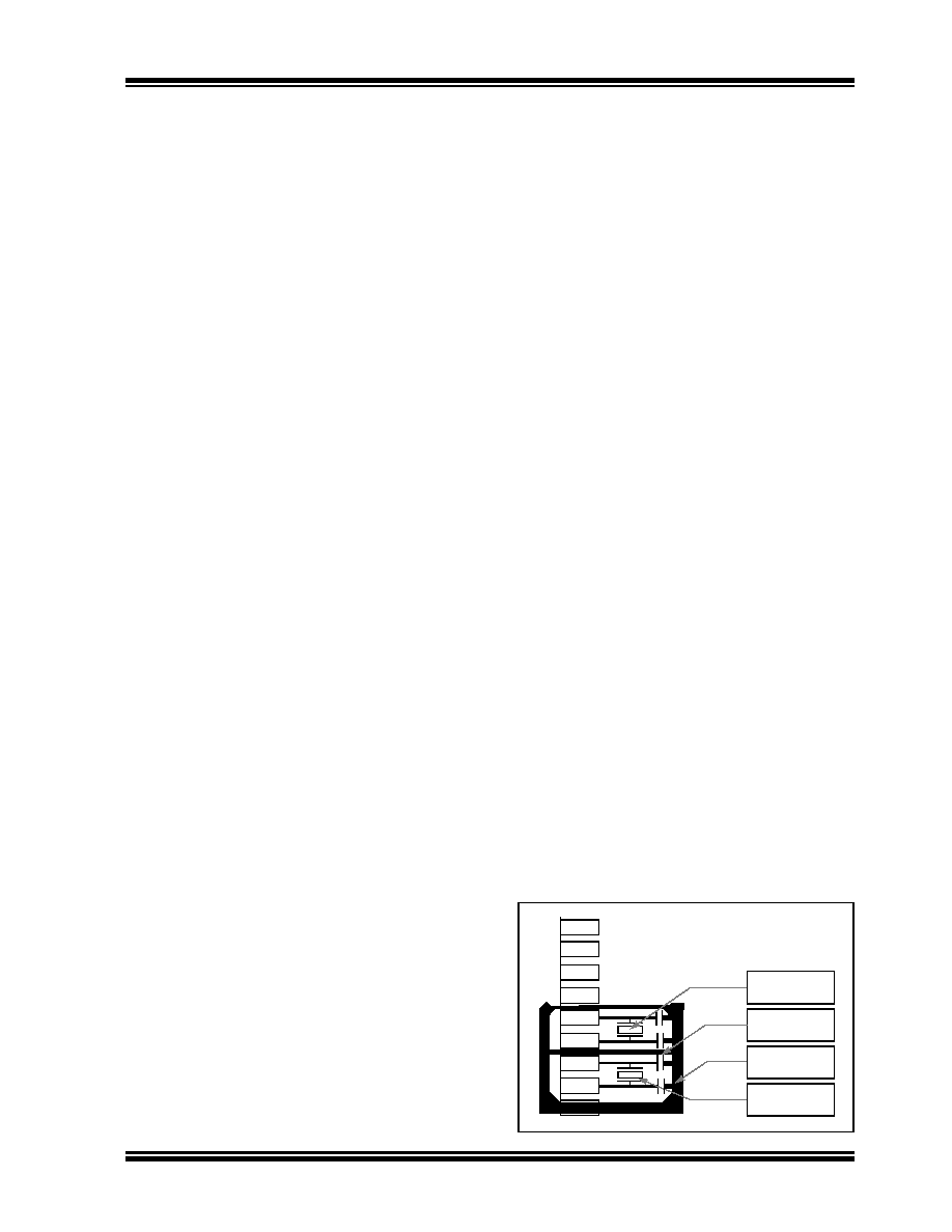
suggested layout is illustrated in Figure 2-3.
FIGURE 2-3:
SUGGESTED PLACEMENT
OF THE OSCILLATOR
CIRCUIT
Main Oscillator
Guard Ring
Guard Trace
Secondary
Oscillator
相关PDF资料 |
PDF描述 |
|---|---|
| RBM18DSUI | CONN EDGECARD 36POS DIP .156 SLD |
| C8051F580DK | KIT DEV C8051F58X/59X MCU FAMILY |
| VE-B53-EY | CONVERTER MOD DC/DC 24V 50W |
| 0210490809 | CABLE JUMPER 1.25MM .305M 11POS |
| GCC22DCST | CONN EDGECARD 44POS DIP .100 SLD |
相关代理商/技术参数 |
参数描述 |
|---|---|
| TDGL002 | 功能描述:开发板和工具包 - PIC / DSPIC chipKIT Uno32 Development Board RoHS:否 制造商:Microchip Technology 产品:Starter Kits 工具用于评估:chipKIT 核心:Uno32 接口类型: 工作电源电压: |
| TDGL003 | 功能描述:开发板和工具包 - PIC / DSPIC chipKIT Max32 Development Board RoHS:否 制造商:Microchip Technology 产品:Starter Kits 工具用于评估:chipKIT 核心:Uno32 接口类型: 工作电源电压: |
| TDGL004 | 功能描述:BOARD CEREBOT 32MX7 PIC32MX795 RoHS:是 类别:编程器,开发系统 >> 通用嵌入式开发板和套件(MCU、DSP、FPGA、CPLD等) 系列:PIC® 32MX 产品培训模块:Blackfin® Processor Core Architecture Overview Blackfin® Device Drivers Blackfin® Optimizations for Performance and Power Consumption Blackfin® System Services 特色产品:Blackfin? BF50x Series Processors 标准包装:1 系列:Blackfin® 类型:DSP 适用于相关产品:ADSP-BF548 所含物品:板,软件,4x4 键盘,光学拨轮,QVGA 触摸屏 LCD 和 40G 硬盘 配用:ADZS-BFBLUET-EZEXT-ND - EZ-EXTENDER DAUGHTERBOARDADZS-BFLLCD-EZEXT-ND - BOARD EXT LANDSCAP LCD INTERFACE 相关产品:ADSP-BF542BBCZ-4A-ND - IC DSP 16BIT 400MHZ 400CSBGAADSP-BF544MBBCZ-5M-ND - IC DSP 16BIT 533MHZ MDDR 400CBGAADSP-BF542MBBCZ-5M-ND - IC DSP 16BIT 533MHZ MDDR 400CBGAADSP-BF542KBCZ-6A-ND - IC DSP 16BIT 600MHZ 400CSBGAADSP-BF547MBBCZ-5M-ND - IC DSP 16BIT 533MHZ MDDR 400CBGAADSP-BF548BBCZ-5A-ND - IC DSP 16BIT 533MHZ 400CSBGAADSP-BF547BBCZ-5A-ND - IC DSP 16BIT 533MHZ 400CSBGAADSP-BF544BBCZ-5A-ND - IC DSP 16BIT 533MHZ 400CSBGAADSP-BF542BBCZ-5A-ND - IC DSP 16BIT 533MHZ 400CSBGA |
| TDGL005 | 功能描述:子卡和OEM板 chipKIT Basic I/O Shield RoHS:否 制造商:BeagleBoard by CircuitCo 产品:BeagleBone LCD4 Boards 用于:BeagleBone - BB-Bone - Open Source Development Kit |
| TDGL006 | 功能描述:界面开发工具 chipKIT Network Shield RoHS:否 制造商:Bourns 产品:Evaluation Boards 类型:RS-485 工具用于评估:ADM3485E 接口类型:RS-485 工作电源电压:3.3 V |
发布紧急采购,3分钟左右您将得到回复。