- 您现在的位置:买卖IC网 > PDF目录372454 > TISP61089B (Electronic Theatre Controls, Inc.) TISP61089B High Voltage Ringing SLIC Protector PDF资料下载
参数资料
| 型号: | TISP61089B |
| 厂商: | Electronic Theatre Controls, Inc. |
| 英文描述: | TISP61089B High Voltage Ringing SLIC Protector |
| 中文描述: | TISP61089B高压振铃用户接口保护 |
| 文件页数: | 18/22页 |
| 文件大小: | 411K |
| 代理商: | TISP61089B |
OCTOBER 2000 - REVISED FEBRUARY 2005
Specifications are subject to change without notice.
Customers should verify actual device performance in their specific applications.
TISP61089B High Voltage Ringing SLIC Protector
Overcurrent and Overvoltage Protection Coordination (Continued)
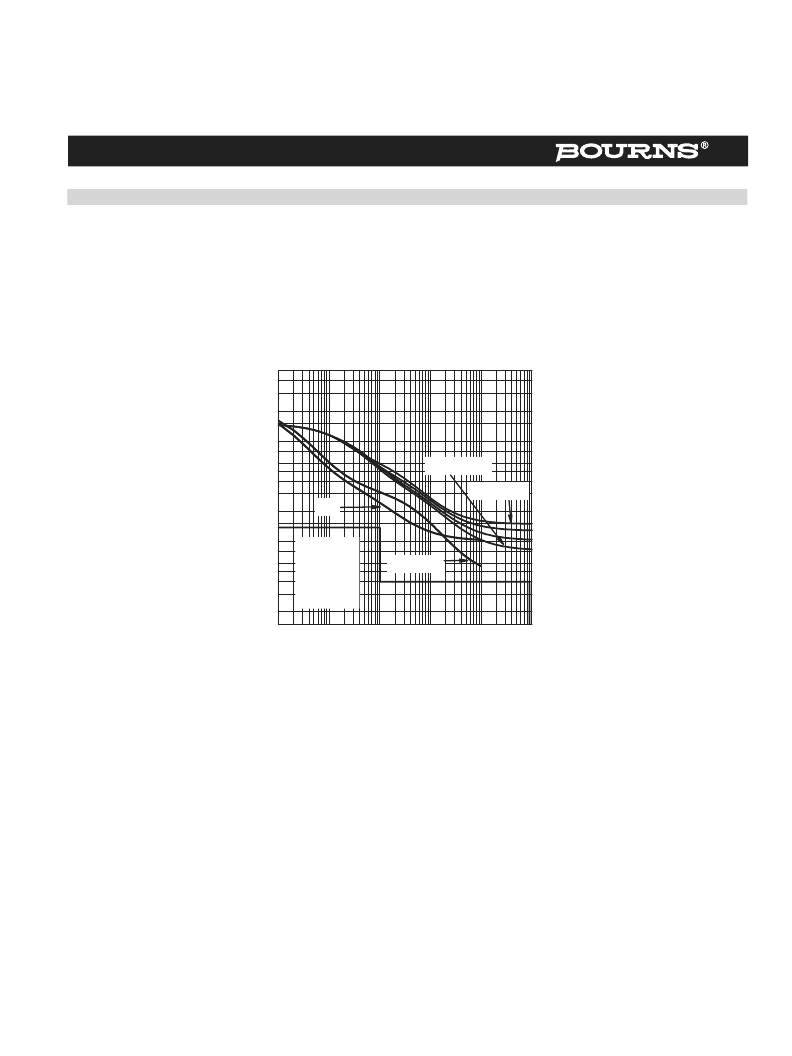
The overcurrent protector should not allow current-time durations greater than the TISP61089B current ratings, otherwise the TISP61089B
may fail. A satisfactory fusible resistor performance is shown in Figure 20. The line feed resistor (LFR) current-time curve is above the first-level
currents and below the TISP61089B rated current for V
GG
> -100 V. This particular curve is for a Bourns 4B04B-523-400 2 x 40
, 2 %
tolerance, 0.5 % matched resistor module. Fusible resistors are also available with integrated thermal fuses or PTC thermistors. Thermal fuses
will cause a rapid drop in the operating current after about 10 s. Figure 20 shows the fused LFR curve for a Bourns 4B04B-524-400 2 x 40
,
2 % tolerance, 0.5 % matched resistor module with integrated thermal fuse links. The Bourns 4B04B-524-400 allows the TISP61089B to
operate down to its full rated voltage of V
GG
= -155 V. An LFR with integrated PTC thermistors will give an automatically resettable current
limiting function for all but the highest currents.
PEAK AC
vs
CURRENT DURATION
50
Figure 20. Line Feed Resistor - with and without Thermal Fuse
t — Current Duration — s
0.01
0.1
1
10
100
1000
P
0.15
0.2
0.3
0.4
0.5
0.8
1.5
2
3
4
5
6
8
15
10
20
30
40
1
AI6XDKA
First Level
Tests # 1
through 5,
25
& 40
Fused LFR
LFR
V
GG
= -60 V
V
GG
= -120 V
Ceramic PTC thermistors are available in suitable ohmic values to be used as the series line feed resistor R
S
. Figure 21 overlays a typical
ceramic PTC thermistor operating characteristic. Some of the first-level tests will cause thermistor operation. Generally, the resistance
matching stability of the two PTC thermistors after power fault switching lightning will meet the required line balance performance.
Ceramic PTC thermistors reduce in resistance value under high voltage conditions. Under high current impulse conditions, the resistance can
be less than 50 % of the d.c. resistance. This means that more current than expected will flow under high voltage impulse conditions. The
manufacturer should be consulted on the 2/10 currents conducted by their product under ‘1089 conditions. To keep the 2/10 current below
120 A, an increase of the PTC thermistor d.c. resistance value to 50
or more may be needed. In controlled temperature environments, where
the temperature does not drop below freezing, the TISP61089B 2/10 capability is about 170 A, and this would allow a lower value of
resistance.
Generally, polymer PTC thermistors are not available in sufficiently high ohmic values to be used as the only line feed resistance. To meet the
required resistance value, an addition (fixed) series resistance can be used. Figure 22 overlays a typical polymer PTC thermistor operating
characteristic. Compared to ceramic PTC thermistors, the lower thermal mass of the polymer type will generally give a faster current reduction
time than the ceramic type. However, in this case the polymer resistance value is much less than the ceramic value. For the same current level,
the dissipation in the polymer thermistor is much less than the ceramic thermistor. As a result, the polymer thermistor is slower to operate than
the ceramic one.
The resistance stability of polymer PTC thermistors is not as good as ceramic ones. However, the thermistor resistance change will be diluted
by additional series resistance. If an SLIC with adaptive line balance is used, thermistor resistance stability may not be a problem. Polymer
PTC thermistors do not have a resistance decrease under high voltage conditions.
相关PDF资料 |
PDF描述 |
|---|---|
| TISP61089BD | TISP61089B High Voltage Ringing SLIC Protector |
| TISP61089BDR | TISP61089B High Voltage Ringing SLIC Protector |
| TISP61089BD-S | TISP61089B High Voltage Ringing SLIC Protector |
| TISP61089BDR-S | TISP61089B High Voltage Ringing SLIC Protector |
| TISP6L7591 | DUAL FORWARD-CONDUCTING P-GATE THYRISTORS PROGRAMMABLE OVERVOLTAGE PROTECTORS |
相关代理商/技术参数 |
参数描述 |
|---|---|
| TISP61089BD | 功能描述:SCR Dual P Gate Forward Conducting RoHS:否 制造商:STMicroelectronics 最大转折电流 IBO:480 A 额定重复关闭状态电压 VDRM:600 V 关闭状态漏泄电流(在 VDRM IDRM 下):5 uA 开启状态 RMS 电流 (It RMS): 正向电压下降:1.6 V 栅触发电压 (Vgt):1.3 V 最大栅极峰值反向电压:5 V 栅触发电流 (Igt):35 mA 保持电流(Ih 最大值):75 mA 安装风格:Through Hole 封装 / 箱体:TO-220 封装:Tube |
| TISP61089BDR | 功能描述:SCR Dual P Gate Forward Conducting RoHS:否 制造商:STMicroelectronics 最大转折电流 IBO:480 A 额定重复关闭状态电压 VDRM:600 V 关闭状态漏泄电流(在 VDRM IDRM 下):5 uA 开启状态 RMS 电流 (It RMS): 正向电压下降:1.6 V 栅触发电压 (Vgt):1.3 V 最大栅极峰值反向电压:5 V 栅触发电流 (Igt):35 mA 保持电流(Ih 最大值):75 mA 安装风格:Through Hole 封装 / 箱体:TO-220 封装:Tube |
| TISP61089BDR-S | 功能描述:SCR Dual P Gate Forward Conducting RoHS:否 制造商:STMicroelectronics 最大转折电流 IBO:480 A 额定重复关闭状态电压 VDRM:600 V 关闭状态漏泄电流(在 VDRM IDRM 下):5 uA 开启状态 RMS 电流 (It RMS): 正向电压下降:1.6 V 栅触发电压 (Vgt):1.3 V 最大栅极峰值反向电压:5 V 栅触发电流 (Igt):35 mA 保持电流(Ih 最大值):75 mA 安装风格:Through Hole 封装 / 箱体:TO-220 封装:Tube |
| TISP61089BDR-T | 功能描述:SCR PROTECTOR - PROGRAMMABLE SLIC PROTECT RoHS:否 制造商:STMicroelectronics 最大转折电流 IBO:480 A 额定重复关闭状态电压 VDRM:600 V 关闭状态漏泄电流(在 VDRM IDRM 下):5 uA 开启状态 RMS 电流 (It RMS): 正向电压下降:1.6 V 栅触发电压 (Vgt):1.3 V 最大栅极峰值反向电压:5 V 栅触发电流 (Igt):35 mA 保持电流(Ih 最大值):75 mA 安装风格:Through Hole 封装 / 箱体:TO-220 封装:Tube |
| TISP61089BDS | 制造商:Bourns Inc 功能描述: |
发布紧急采购,3分钟左右您将得到回复。