- 您现在的位置:买卖IC网 > PDF目录67344 > TL5001QD (TEXAS INSTRUMENTS INC) 0.1 A SWITCHING CONTROLLER, 500 kHz SWITCHING FREQ-MAX, PDSO8 PDF资料下载
参数资料
| 型号: | TL5001QD |
| 厂商: | TEXAS INSTRUMENTS INC |
| 元件分类: | 稳压器 |
| 英文描述: | 0.1 A SWITCHING CONTROLLER, 500 kHz SWITCHING FREQ-MAX, PDSO8 |
| 封装: | PLASTIC, MS-012AA, SOIC-8 |
| 文件页数: | 23/31页 |
| 文件大小: | 745K |
| 代理商: | TL5001QD |
第1页第2页第3页第4页第5页第6页第7页第8页第9页第10页第11页第12页第13页第14页第15页第16页第17页第18页第19页第20页第21页第22页当前第23页第24页第25页第26页第27页第28页第29页第30页第31页
TL5001, TL5001A
PULSE-WIDTH-MODULATION CONTROL CIRCUITS
SLVS084F – APRIL 1994 – REVISED JANUARY 2002
3
POST OFFICE BOX 655303
DALLAS, TEXAS 75265
detailed description
voltage reference
A 2.5-V regulator operating from VCC is used to power the internal circuitry of the TL5001 and TL5001A and as a
reference for the error amplifier and SCP circuits. A resistive divider provides a 1-V reference for the error amplifier
noninverting input which typically is within 2% of nominal over the operating temperature range.
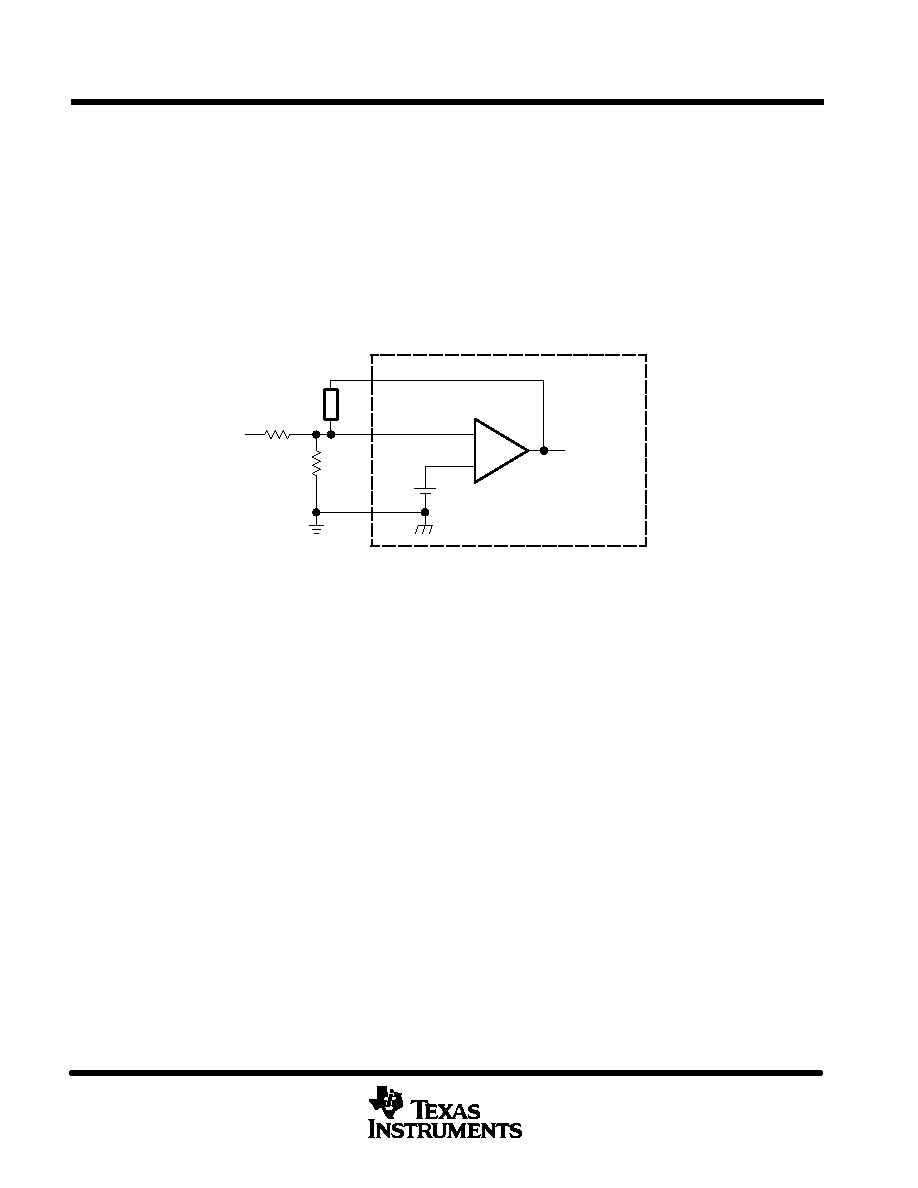
error amplifier
The error amplifier compares a sample of the dc-to-dc converter output voltage to the 1-V reference and generates
an error signal for the PWM comparator. The dc-to-dc converter output voltage is set by selecting the error-amplifier
gain (see Figure 1), using the following expression:
VO = (1 + R1/R2) (1 V)
To PWM
Comparator
Vref = 1 V
4
VI(FB)
3
+
–
R2
R1
COMP
FB
Compensation
Network
TL5001/A
GND
8
Figure 1. Error-Amplifier Gain Setting
The error-amplifier output is brought out as COMP for use in compensating the dc-to-dc converter control loop for
stability. Because the amplifier can only source 45
A, the total dc load resistance should be 100 k or more.
oscillator/PWM
The oscillator frequency (fosc) can be set between 20 kHz and 500 kHz by connecting a resistor between RT and
GND. Acceptable resistor values range from 15 k
to 250 k. The oscillator frequency can be determined by using
the graph shown in Figure 5.
The oscillator output is a triangular wave with a minimum value of approximately 0.7 V and a maximum value of
approximately 1.3 V. The PWM comparator compares the error-amplifier output voltage and the DTC input voltage
to the triangular wave and turns the output transistor off whenever the triangular wave is greater than the lesser of
the two inputs.
dead-time control (DTC)
DTC provides a means of limiting the output-switch duty cycle to a value less than 100 %, which is critical for boost
and flyback converters. A current source generates a reference current (IDT) at DTC that is nominally equal to the
current at the oscillator timing terminal, RT. Connecting a resistor between DTC and GND generates a dead-time
reference voltage (VDT), which the PWM/DTC comparator compares to the oscillator triangle wave as described
in the previous section. Nominally, the maximum duty cycle is 0 % when VDT is 0.7 V or less and 100% when VDT
is 1.3 V or greater. Because the triangle wave amplitude is a function of frequency and the source impedance of
RT is relatively high (1250
), choosing RDT for a specific maximum duty cycle, D, is accomplished using the
following equation and the voltage limits for the frequency in question as found in Figure 11 (Voscmax and Voscmin
are the maximum and minimum oscillator levels):
相关PDF资料 |
PDF描述 |
|---|---|
| TL5001IPE4 | 0.1 A SWITCHING CONTROLLER, 500 kHz SWITCHING FREQ-MAX, PDIP8 |
| TL5001CD | 0.1 A SWITCHING CONTROLLER, 500 kHz SWITCHING FREQ-MAX, PDSO8 |
| TL5001CPSR | 0.1 A SWITCHING CONTROLLER, 500 kHz SWITCHING FREQ-MAX, PDSO8 |
| TL5001ACDR | 0.1 A SWITCHING CONTROLLER, 500 kHz SWITCHING FREQ-MAX, PDSO8 |
| TL5001AQDG4 | 0.1 A SWITCHING CONTROLLER, 500 kHz SWITCHING FREQ-MAX, PDSO8 |
相关代理商/技术参数 |
参数描述 |
|---|---|
| TL5001QDG4 | 功能描述:软开关 PWM 控制器 PWM Controller w/ Wide Input Range RoHS:否 制造商:Fairchild Semiconductor 输出端数量: 输出电流: 开关频率: 工作电源电压:30 V 电源电流: 最大工作温度:+ 105 C 最小工作温度:- 40 C 安装风格:SMD/SMT 封装 / 箱体:SOIC-8 封装:Reel |
| TL5001QDR | 功能描述:软开关 PWM 控制器 withWide Input Voltage Range RoHS:否 制造商:Fairchild Semiconductor 输出端数量: 输出电流: 开关频率: 工作电源电压:30 V 电源电流: 最大工作温度:+ 105 C 最小工作温度:- 40 C 安装风格:SMD/SMT 封装 / 箱体:SOIC-8 封装:Reel |
| TL5001QDRG4 | 功能描述:软开关 PWM 控制器 PWM Controller w/ Wide Input Range RoHS:否 制造商:Fairchild Semiconductor 输出端数量: 输出电流: 开关频率: 工作电源电压:30 V 电源电流: 最大工作温度:+ 105 C 最小工作温度:- 40 C 安装风格:SMD/SMT 封装 / 箱体:SOIC-8 封装:Reel |
| TL5001-S08-R | 制造商:UTC-IC 制造商全称:UTC-IC 功能描述:PULSE-WIDTH-MODULATION CONTROL CIRCUITS |
| TL5001-S08-T | 制造商:UTC-IC 制造商全称:UTC-IC 功能描述:PULSE-WIDTH-MODULATION CONTROL CIRCUITS |
发布紧急采购,3分钟左右您将得到回复。