- 您现在的位置:买卖IC网 > PDF目录225319 > TLC2934IPWRG4 (TEXAS INSTRUMENTS INC) PHASE LOCKED LOOP, 130 MHz, PDSO14 PDF资料下载
参数资料
| 型号: | TLC2934IPWRG4 |
| 厂商: | TEXAS INSTRUMENTS INC |
| 元件分类: | PLL合成/DDS/VCOs |
| 英文描述: | PHASE LOCKED LOOP, 130 MHz, PDSO14 |
| 封装: | PLASTIC, SOP-14 |
| 文件页数: | 1/10页 |
| 文件大小: | 168K |
| 代理商: | TLC2934IPWRG4 |
TLC2934
3.3 V 130 MHZ VCO, PHASE FREQUENCY DETECTOR
SLAS306 – NOVEMBER 2000
1
POST OFFICE BOX 655303
DALLAS, TEXAS 75265
D Voltage-Controlled Oscillator (VCO)
–
Ring Oscillator Using Only One
External Biasing Resistor (RBIAS)
D Recommended Lock Frequency
– 100 MHz to 130 MHz
– (VDD = 3.3 V + 5%, TA = –20°C to 75°C)
D Phase-Frequency Detector (PFD)
Includes a High-Speed Edge-Triggered
Detector With Internal Charge Pump
D Independent VCO, PFD Power-Down
Mode
D Thin Small-Outline Package (14
Terminal)
D Compatible Pin Assignment to
TLC2932, TLC2933
description
The TLC2934, a mixed signal IC designed for phase-locked-loop (PLL) systems, is composed of a
voltage-controlled oscillator (VCO) and an edge-triggered-type phase frequency detector (PFD).
The internal VCO is based on the TLC2932 and TLC2933s ring oscillator. It oscillates in wider frequency with
lower supply voltage, and it has stable oscillating performance. The oscillation function, provided by only one
external resistor connection, supplies bias to the VCI internal circuit. Oscillator range is covered from 10 MHz
to 130 MHz with a 3.3-V supply voltage. The VCO has an inhibit function to stop oscillation and for the
power-down mode.
The internal PFD, a high-speed rising edge triggered type, has an internal charge pump with a high-impedance
output buffer. The PFD detects phase difference between the reference frequency input and the signal
frequency input from the VCO output through an external counter device. This functions the same as TLC2932
and TLC2933. The PFD also has the inhibit function for stop phase comparison and for power-down mode.
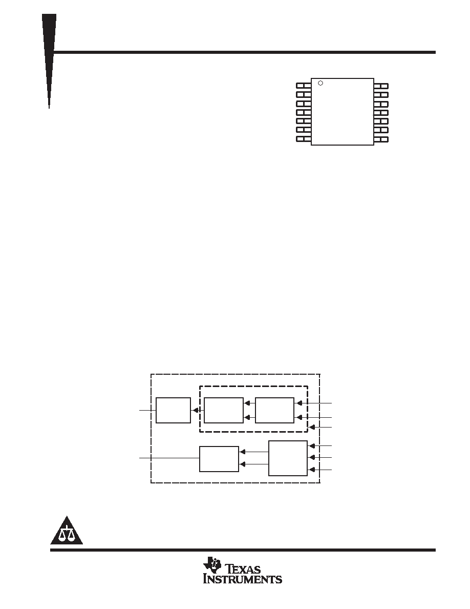
block diagram
Through
or 1/2
Ring
Oscillator
Bias
Control
VCO
PFD
Ring
Oscillator
TLC29341PW
f(OSC)
PFD OUT
Bias Supply
Control Voltage
VCO INHIBIT
Reference Input
Comparison Input
PFD INHIBIT
Copyright
2000, Texas Instruments Incorporated
PRODUCTION DATA information is current as of publication date.
Products conform to specifications per the terms of Texas Instruments
standard warranty. Production processing does not necessarily include
testing of all parameters.
Please be aware that an important notice concerning availability, standard warranty, and use in critical applications of
Texas Instruments semiconductor products and disclaimers thereto appears at the end of this data sheet.
1
2
3
4
5
6
7
14
13
12
11
10
9
8
LOGIC VDD
SELECT
VCO OUT
FIN -A
FIN -B
PFD OUT
LOGIC GND
VCO VDD
RBIAS
VCO IN
VCO GND
VCO INHIBIT
PFD INHIBIT
TEST
PW PACKAGE
(TOP VIEW)
相关PDF资料 |
PDF描述 |
|---|---|
| TLE4250G | POWER SUPPLY SUPPORT CKT, PDSO5 |
| TLE6208-3G | BRUSH DC MOTOR CONTROLLER, PDSO14 |
| TLE7368G | 1-CHANNEL POWER SUPPLY MANAGEMENT CKT, PDSO36 |
| TLGE158P(Q) | T-1 3/4 SINGLE COLOR LED, HIGH INTENSITY GREEN, 5 mm |
| TLHY4601BT21 | T-1 SINGLE COLOR LED, YELLOW, 3 mm |
相关代理商/技术参数 |
参数描述 |
|---|---|
| TLC2940IPW | 制造商:Rochester Electronics LLC 功能描述:- Bulk 制造商:Texas Instruments 功能描述: |
| TLC2942IDB | 制造商:Rochester Electronics LLC 功能描述:- Bulk |
| TLC2942IDBR | 制造商:Rochester Electronics LLC 功能描述:- Bulk |
| TLC2943IDB | 制造商:Rochester Electronics LLC 功能描述:- Bulk |
| TLC-2C-0164 | 制造商:KATO/COILTHREAD 功能描述: |
发布紧急采购,3分钟左右您将得到回复。