- 您现在的位置:买卖IC网 > PDF目录98241 > TLC5510INSR (TEXAS INSTRUMENTS INC) 1-CH 8-BIT FLASH METHOD ADC, PARALLEL ACCESS, PDSO24 PDF资料下载
参数资料
| 型号: | TLC5510INSR |
| 厂商: | TEXAS INSTRUMENTS INC |
| 元件分类: | ADC |
| 英文描述: | 1-CH 8-BIT FLASH METHOD ADC, PARALLEL ACCESS, PDSO24 |
| 封装: | GREEN, PLASTIC, SOP-24 |
| 文件页数: | 20/21页 |
| 文件大小: | 500K |
| 代理商: | TLC5510INSR |
TLC5510, TLC5510A
8-BIT HIGH-SPEED ANALOG-TO-DIGITAL CONVERTERS
SLAS095L – SEPTEMBER 1994 – REVISED JUNE 2003
8
POST OFFICE BOX 655303
DALLAS, TEXAS 75265
PRINCIPLES OF OPERATION
functional operation
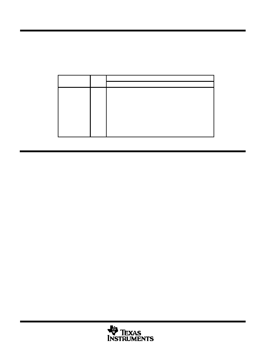
The output code change with input voltage is shown in Table 1.
Table 1. Functional Operation
INPUT SIGNAL
STEP
DIGITAL OUTPUT CODE
INPUT SIGNAL
VOLTAGE
STEP
MSB
LSB
Vref(B)
255
0
128
0
11
1
127
1
00
0
Vref(T)
0
1
APPLICATION INFORMATION
The following notes are design recommendations that should be used with the device.
D External analog and digital circuitry should be physically separated and shielded as much as possible to
reduce system noise.
D RF breadboarding or printed-circuit-board (PCB) techniques should be used throughout the evaluation and
production process. Breadboards should be copper clad for bench evaluation.
D Since AGND and DGND are connected internally, the ground lead in must be kept as noise free as possible.
A good method to use is twisted-pair cables for the supply lines to minimize noise pickup. An analog and
digital ground plane should be used on PCB layouts when additional logic devices are used. The AGND
and DGND terminals of the device should be tied to the analog ground plane.
D VDDA to AGND and VDDD to DGND should be decoupled with 1-F and 0.01-F capacitors, respectively,
and placed as close as possible to the affected device terminals. A ceramic-chip capacitor is recommended
for the 0.01-
F capacitor. Care should be exercised to ensure a solid noise-free ground connection for the
analog and digital ground terminals.
D VDDA, AGND, and ANALOG IN should be shielded from the higher frequency terminals, CLK and D0–D7.
When possible, AGND traces should be placed on both sides of the ANALOG IN traces on the PCB for
shielding.
D In testing or application of the device, the resistance of the driving source connected to the analog input
should be 10
or less within the analog frequency range of interest.
相关PDF资料 |
PDF描述 |
|---|---|
| TLC5510IPWR | 1-CH 8-BIT FLASH METHOD ADC, PARALLEL ACCESS, PDSO24 |
| TLC5510AINSRG4 | 1-CH 8-BIT FLASH METHOD ADC, PARALLEL ACCESS, PDSO24 |
| TLC5510IPWRG4 | 1-CH 8-BIT FLASH METHOD ADC, PARALLEL ACCESS, PDSO24 |
| TLC5510INSLE | 1-CH 8-BIT FLASH METHOD ADC, PARALLEL ACCESS, PDSO24 |
| TLC5510IPWG4 | 1-CH 8-BIT FLASH METHOD ADC, PARALLEL ACCESS, PDSO24 |
相关代理商/技术参数 |
参数描述 |
|---|---|
| TLC5510INSR-A | 制造商:Rochester Electronics LLC 功能描述:- Bulk |
| TLC5510INSRG4 | 功能描述:模数转换器 - ADC 8-Bit 20 MSPS 1-Ch Internal S&H Lo Pwr RoHS:否 制造商:Texas Instruments 通道数量:2 结构:Sigma-Delta 转换速率:125 SPs to 8 KSPs 分辨率:24 bit 输入类型:Differential 信噪比:107 dB 接口类型:SPI 工作电源电压:1.7 V to 3.6 V, 2.7 V to 5.25 V 最大工作温度:+ 85 C 安装风格:SMD/SMT 封装 / 箱体:VQFN-32 |
| TLC5510IPW | 功能描述:模数转换器 - ADC 8bit 20Msps 1ch 5V RoHS:否 制造商:Texas Instruments 通道数量:2 结构:Sigma-Delta 转换速率:125 SPs to 8 KSPs 分辨率:24 bit 输入类型:Differential 信噪比:107 dB 接口类型:SPI 工作电源电压:1.7 V to 3.6 V, 2.7 V to 5.25 V 最大工作温度:+ 85 C 安装风格:SMD/SMT 封装 / 箱体:VQFN-32 |
| TLC5510IPWG4 | 功能描述:视频模拟/数字化转换器集成电路 8-Bit 20 MSPS 1-Ch Internal S&H Lo Pwr RoHS:否 制造商:Texas Instruments 输入信号类型:Differential 转换器数量:1 ADC 输入端数量:4 转换速率:3 Gbps 分辨率:8 bit 结构: 输入电压:3.3 V 接口类型:SPI 信噪比: 电压参考: 电源电压-最大:3.45 V 电源电压-最小:3.15 V 最大功率耗散: 最大工作温度:+ 85 C 最小工作温度:- 40 C 封装 / 箱体:TCSP-48 封装:Reel |
| TLC5510IPWR | 功能描述:模数转换器 - ADC 8-Bit 20 MSPS 1-Ch Internal S&H Lo Pwr RoHS:否 制造商:Texas Instruments 通道数量:2 结构:Sigma-Delta 转换速率:125 SPs to 8 KSPs 分辨率:24 bit 输入类型:Differential 信噪比:107 dB 接口类型:SPI 工作电源电压:1.7 V to 3.6 V, 2.7 V to 5.25 V 最大工作温度:+ 85 C 安装风格:SMD/SMT 封装 / 箱体:VQFN-32 |
发布紧急采购,3分钟左右您将得到回复。