- 您现在的位置:买卖IC网 > PDF目录98253 > TLV320AIC23BIGQER (TEXAS INSTRUMENTS INC) SPECIALTY CONSUMER CIRCUIT, PBGA80 PDF资料下载
参数资料
| 型号: | TLV320AIC23BIGQER |
| 厂商: | TEXAS INSTRUMENTS INC |
| 元件分类: | 消费家电 |
| 英文描述: | SPECIALTY CONSUMER CIRCUIT, PBGA80 |
| 封装: | PLASTIC, VFBGA-80 |
| 文件页数: | 6/54页 |
| 文件大小: | 795K |
| 代理商: | TLV320AIC23BIGQER |
第1页第2页第3页第4页第5页当前第6页第7页第8页第9页第10页第11页第12页第13页第14页第15页第16页第17页第18页第19页第20页第21页第22页第23页第24页第25页第26页第27页第28页第29页第30页第31页第32页第33页第34页第35页第36页第37页第38页第39页第40页第41页第42页第43页第44页第45页第46页第47页第48页第49页第50页第51页第52页第53页第54页
23
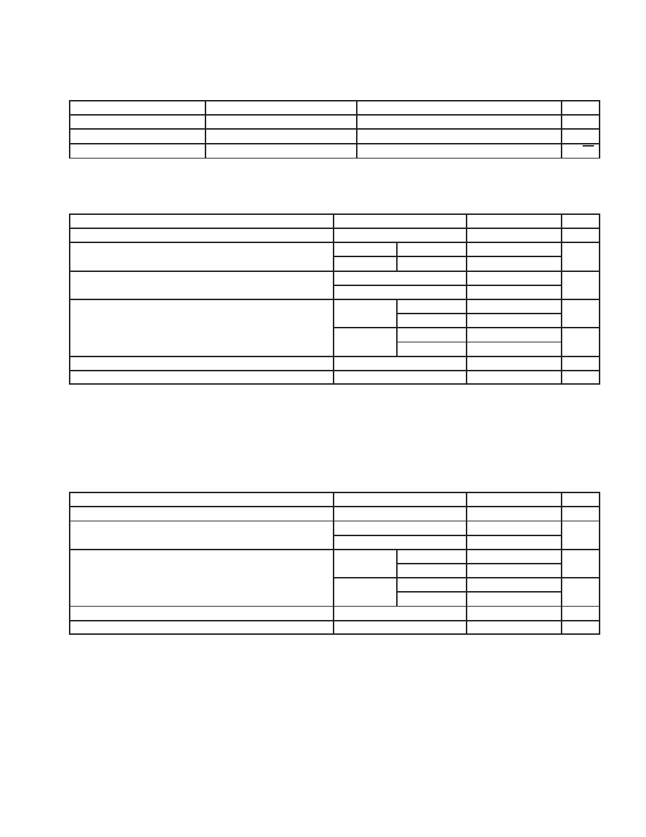
2.3.1.3 Microphone Bias
PARAMETER
TEST CONDITIONS
MIN
TYP
MAX
UNIT
Bias voltage
3/4 AVDD 100 m
3/4 AVDD
3/4 AVDD + 100 m
V
Bias-current source
3
mA
Output noise voltage
1 kHz to 20 kHz
25
nV/
√Hz
2.3.2
DAC
2.3.2.1 Line Output, Load = 10 k
, 50 pF
PARAMETER
TEST CONDITIONS
MIN
TYP
MAX
UNIT
0-dB full-scale output voltage (FFFFFF)
1.0
VRMS
Signal-to-noise ratio, A-weighted, 0-dB gain (see Notes 3, 4, and 5)
AVDD = 3.3 V
fs = 48kHz
90
100
dB
Signal-to-noise ratio, A-weighted, 0-dB gain (see Notes 3, 4, and 5)
AVDD = 2.7 V
fs = 48 kHz
100
dB
Dynamic range, A-weighted (see Note 4)
AVDD = 3.3 V
85
90
dB
Dynamic range, A-weighted (see Note 4)
AVDD = 2.7 V
TBD
dB
AVDD = 3.3 V
1 kHz, 0 dB
–88
–80
dB
Total harmonic distortion
AVDD = 3.3 V
1 kHz, 3 dB
92
86
dB
Total harmonic distortion
AVDD = 2.7 V
1 kHz, 0 dB
85
dB
AVDD = 2.7 V
1 kHz, 3 dB
88
dB
Power supply rejection ratio
1 kHz, 100 mVpp
50
dB
DAC channel separation
100
dB
NOTES:
3. Ratio of output level with 1-kHz full-scale input, to the output level with the input short circuited, measured A-weighted over a 20-Hz
to 20-kHz bandwidth using an audio analyzer.
4. All performance measurements done with 20-kHz low-pass filter and, where noted, A-weighted filter. Failure to use such a filter
results in higher THD + N and lower SNR and dynamic range readings than shown in the Electrical Characteristics. The low-pass
filter removes out-of-band noise, which, although not audible, may affect dynamic specification values.
5. Ratio of output level with 1-kHz full-scale input, to the output level with all zeros into the digital input, measured A-weighted over
a 20-Hz to 20-kHz bandwidth.
2.3.3
Analog Line Input to Line Output (Bypass)
PARAMETER
TEST CONDITIONS
MIN
TYP
MAX
UNIT
0-dB full-scale output voltage
1.0
VRMS
Signal-to-noise ratio, A-weighted, 0-dB gain (see Notes 3 and 4)
AVDD = 3.3 V
90
95
dB
Signal-to-noise ratio, A-weighted, 0-dB gain (see Notes 3 and 4)
AVDD = 2.7 V
95
dB
AVDD = 3.3 V
1 kHz, 0 dB
–86
–80
dB
Total harmonic distortion
AVDD = 3.3 V
1 kHz, 3 dB
92
86
dB
Total harmonic distortion
AVDD = 2.7 V
1 kHz, 0 dB
86
dB
AVDD = 2.7 V
1 kHz, 3 dB
92
dB
Power supply rejection ratio
1 kHz, 100 mVpp
50
dB
DAC channel separation (left to right)
1 kHz, 0 dB
80
dB
NOTES:
3. Ratio of output level with 1-kHz full-scale input, to the output level with the input short circuited, measured A-weighted over a 20-Hz
to 20-kHz bandwidth using an audio analyzer.
4. All performance measurements done with 20-kHz low-pass filter and, where noted, A-weighted filter. Failure to use such a filter
results in higher THD + N and lower SNR and dynamic range readings than shown in the Electrical Characteristics. The low-pass
filter removes out-of-band noise, which, although not audible, may affect dynamic specification values.
相关PDF资料 |
PDF描述 |
|---|---|
| TLV320AIC23BIPWR | SPECIALTY CONSUMER CIRCUIT, PDSO28 |
| TLV320AIC23BIRHD | SPECIALTY CONSUMER CIRCUIT, PQCC28 |
| TLV320AIC23BIZQE | SPECIALTY CONSUMER CIRCUIT, PBGA80 |
| TLV320AIC23BPWR | SPECIALTY CONSUMER CIRCUIT, PDSO28 |
| TLV320AIC23BRHD | SPECIALTY CONSUMER CIRCUIT, PQCC28 |
相关代理商/技术参数 |
参数描述 |
|---|---|
| TLV320AIC23BIPW | 功能描述:接口—CODEC Lo-Pwr Highly Integrated Codec RoHS:否 制造商:Texas Instruments 类型: 分辨率: 转换速率:48 kSPs 接口类型:I2C ADC 数量:2 DAC 数量:4 工作电源电压:1.8 V, 2.1 V, 2.3 V to 5.5 V 最大工作温度:+ 85 C 安装风格:SMD/SMT 封装 / 箱体:DSBGA-81 封装:Reel |
| TLV320AIC23BIPW | 制造商:Texas Instruments 功能描述:IC CODEC AUDIO SMD TSSOP28 320 |
| TLV320AIC23BIPWG4 | 功能描述:接口—CODEC Lo-Pwr Highly Integrated Codec RoHS:否 制造商:Texas Instruments 类型: 分辨率: 转换速率:48 kSPs 接口类型:I2C ADC 数量:2 DAC 数量:4 工作电源电压:1.8 V, 2.1 V, 2.3 V to 5.5 V 最大工作温度:+ 85 C 安装风格:SMD/SMT 封装 / 箱体:DSBGA-81 封装:Reel |
| TLV320AIC23BIPWR | 功能描述:接口—CODEC Lo-Pwr Highly Integrated Codec RoHS:否 制造商:Texas Instruments 类型: 分辨率: 转换速率:48 kSPs 接口类型:I2C ADC 数量:2 DAC 数量:4 工作电源电压:1.8 V, 2.1 V, 2.3 V to 5.5 V 最大工作温度:+ 85 C 安装风格:SMD/SMT 封装 / 箱体:DSBGA-81 封装:Reel |
| TLV320AIC23BIPWRDL | 制造商:TI 功能描述:Stereo Audio Codex |
发布紧急采购,3分钟左右您将得到回复。