- 您现在的位置:买卖IC网 > PDF目录98253 > TLV320AIC27CPFB (TEXAS INSTRUMENTS INC) SPECIALTY CONSUMER CIRCUIT, PQFP48 PDF资料下载
参数资料
| 型号: | TLV320AIC27CPFB |
| 厂商: | TEXAS INSTRUMENTS INC |
| 元件分类: | 消费家电 |
| 英文描述: | SPECIALTY CONSUMER CIRCUIT, PQFP48 |
| 封装: | PLASTIC, TQFP-48 |
| 文件页数: | 17/54页 |
| 文件大小: | 732K |
| 代理商: | TLV320AIC27CPFB |
第1页第2页第3页第4页第5页第6页第7页第8页第9页第10页第11页第12页第13页第14页第15页第16页当前第17页第18页第19页第20页第21页第22页第23页第24页第25页第26页第27页第28页第29页第30页第31页第32页第33页第34页第35页第36页第37页第38页第39页第40页第41页第42页第43页第44页第45页第46页第47页第48页第49页第50页第51页第52页第53页第54页
TLV320AIC27
STEREO AUDIO CODEC
SLAS253A – MARCH 2000 – REVISED SEPTEMBER 2000
24
POST OFFICE BOX 655303
DALLAS, TEXAS 75265
ac-link audio input frame (SDATA_IN) (continued)
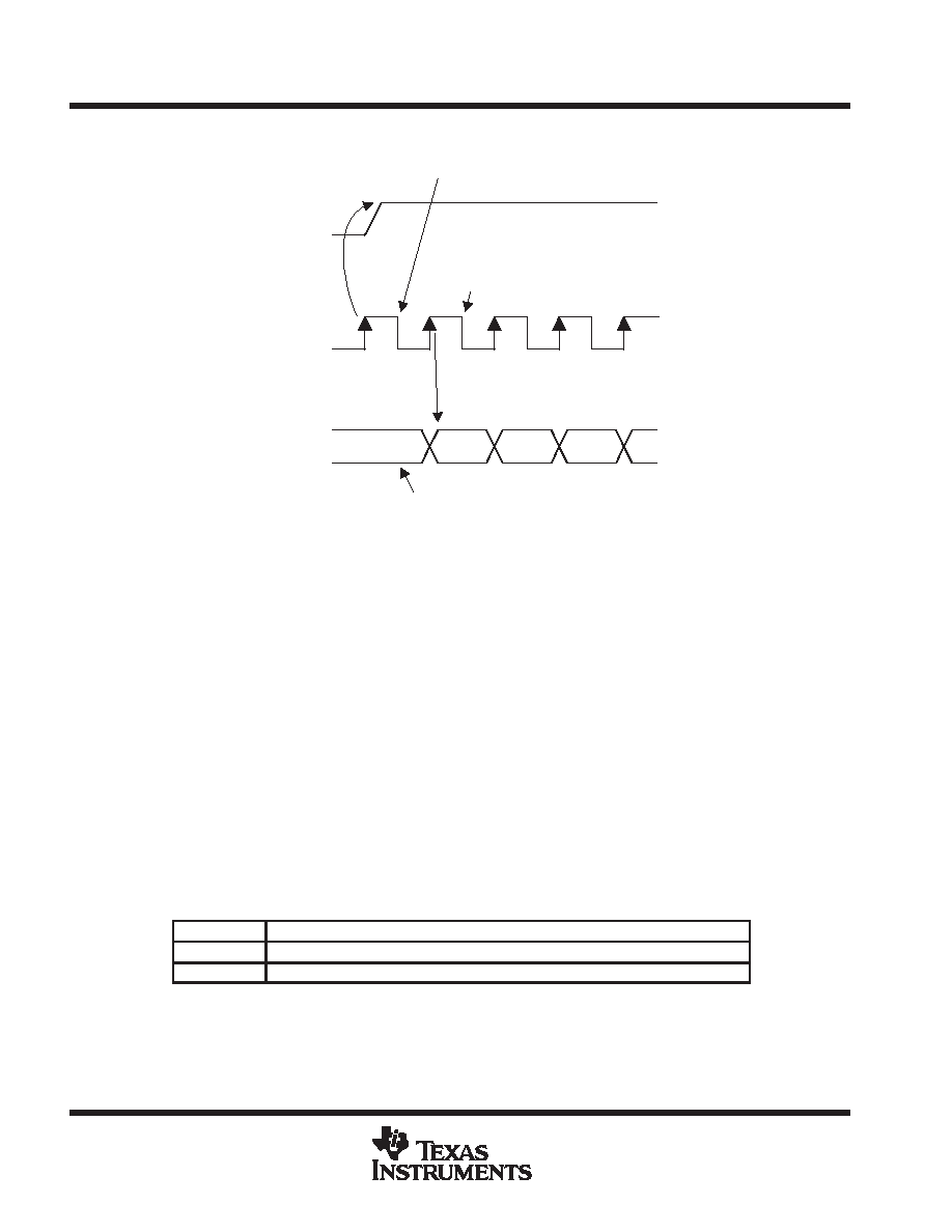
SYNC
BIT_CLK
SDATA_IN
CODEC
READY
SLOT (1)
SLOT (2)
AIC27 SAMPLES
SYNC ASSERTION HERE
AC ’97 CONTROLLER
SAMPLES FIRST SDATA_IN
BIT OF FRAME HERE
END OF PREVIOUS AUDIO FRAME
Figure 12. Start of an Audio Input Frame
A new audio input frame begins with a low-to-high transition of SYNC, as illustrated in Figure 12. SYNC is
synchronous with the rising edge of BIT_CLK. The TLV320AIC27 samples the assertion of SYNC on the next
falling edge of BIT_CLK. This falling edge marks the time when both sides of the ac link are aware of the start
of a new audio frame. The AC’97 controller transitions SDATA_IN into the first bit position of slot 0 (valid frame
bit) on the next rising edge of BIT_CLK. Each new bit position is presented to the ac link on a rising edge of
BIT_CLK, and subsequently sampled by the AC’97 controller on the following falling edge of BIT_CLK. This
sequence ensures that data transitions and subsequent sample points for both incoming and outgoing data
streams are time-aligned.
SDATA_IN’s composite stream is MSB-justified (MSB first), with all invalid bit positions (for assigned and/or
unassigned time slots) stuffed with 0’s by the TLV320AIC27. SDATA_IN is sampled on the falling edges of
BIT_CLK.
slot 1: status address port
The status port is used to monitor the status of the TLV320AIC27 functions,, including, but not limited to, mixer
settings and power management. Audio input frame slot 1 echoes the control register index, for historical
reference, so that the data is returned to slot 2 (assuming that slots 1 and 2 had been tagged valid by the
TLV320AIC27 during slot 0).
Status Address Port Bit Assignments
Bit (19)
Reserved (stuffed with 0s)
Bit (18:12)
Control register index (echo of register index for which data is being returned)
Bit (11:0)
Reserved (stuffed with 0s)
The first bit (MSB) generated by the TLV320AIC27 is always stuffed with a 0. The following 7 bit positions
communicate the associated control register address, and the trailing 12 bit positions are stuffed with 0s by the
TLV320AIC27.
相关PDF资料 |
PDF描述 |
|---|---|
| TLV320AIC27IPFB | SPECIALTY CONSUMER CIRCUIT, PQFP48 |
| TLV320AIC27TPFB | SPECIALTY CONSUMER CIRCUIT, PQFP48 |
| TLV320AIC28IRGZR | SPECIALTY CONSUMER CIRCUIT, PQCC48 |
| TLV320AIC28IRGZ | SPECIALTY CONSUMER CIRCUIT, PQCC48 |
| TLV320AIC28IRGZRG4 | SPECIALTY CONSUMER CIRCUIT, PQCC48 |
相关代理商/技术参数 |
参数描述 |
|---|---|
| TLV320AIC27IPFB | 制造商:TI 制造商全称:Texas Instruments 功能描述:STEREO AUDIO CODEC |
| TLV320AIC27PFB | 制造商:TI 制造商全称:Texas Instruments 功能描述:STEREO AUDIO CODEC |
| TLV320AIC27TPFB | 制造商:Rochester Electronics LLC 功能描述:- Bulk 制造商:Texas Instruments 功能描述: |
| TLV320AIC28 | 制造商:TI 制造商全称:Texas Instruments 功能描述:STEREO AUDIO CODEC WITH INTERGRATED HEADPHONE AND SPEAKER AMPLIFIERS |
| TLV320AIC28_08 | 制造商:TI 制造商全称:Texas Instruments 功能描述:STEREO AUDIO CODEC WITH INTEGRATED HEADPHONE AND SPEAKER AMPLIFIERS |
发布紧急采购,3分钟左右您将得到回复。