- 您现在的位置:买卖IC网 > PDF目录98266 > TMDS261BPAGR (TEXAS INSTRUMENTS INC) SPECIALTY CONSUMER CIRCUIT, PQFP64 PDF资料下载
参数资料
| 型号: | TMDS261BPAGR |
| 厂商: | TEXAS INSTRUMENTS INC |
| 元件分类: | 消费家电 |
| 英文描述: | SPECIALTY CONSUMER CIRCUIT, PQFP64 |
| 封装: | GREEN, PLASTIC, TQFP-64 |
| 文件页数: | 25/49页 |
| 文件大小: | 11321K |
| 代理商: | TMDS261BPAGR |
第1页第2页第3页第4页第5页第6页第7页第8页第9页第10页第11页第12页第13页第14页第15页第16页第17页第18页第19页第20页第21页第22页第23页第24页当前第25页第26页第27页第28页第29页第30页第31页第32页第33页第34页第35页第36页第37页第38页第39页第40页第41页第42页第43页第44页第45页第46页第47页第48页第49页
up(min)
DD
R
V
/ Isink
=
(1)
t
k
RC
=
(2)
(
)
t/RC
DD
V(t)
V
1 e
-
=
-
(3)
www.ti.com .......................................................................................................................................................................................... SLLS987 – SEPTEMBER 2009
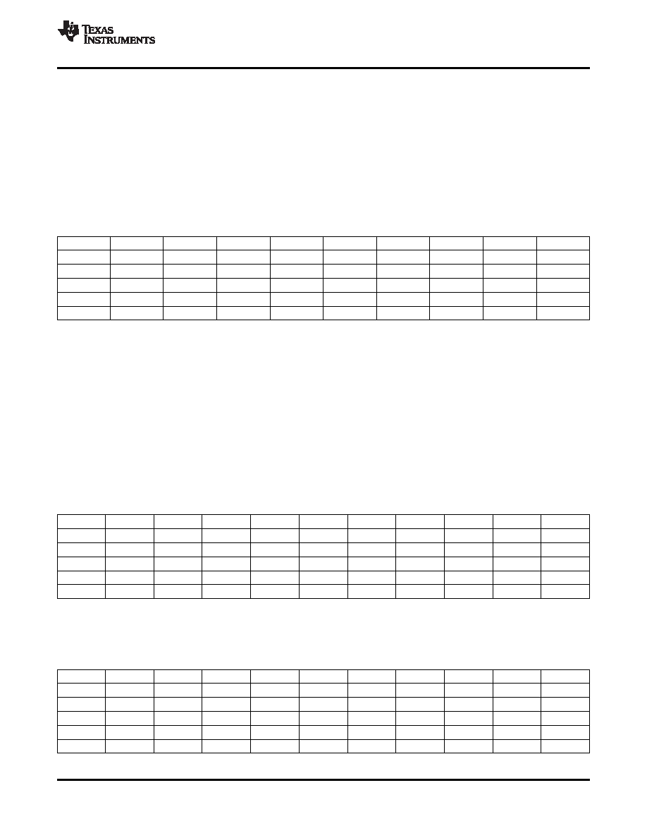
2. The maximum transition time on the bus:
The maximum transition time, T, of an I2C bus is set by an RC time constant, where R is the pullup resistor
value and C is the total load capacitance. The parameter, k, can be calculated from Equation 3 by solving for
t, the times at which certain voltage thresholds are reached. Different input threshold combinations introduce
different values of t. Table 4 summarizes the possible values of k under different threshold combinations.
Table 4. Value of k for Different Input Threshold Voltages
Vth–\Vth+
0.7 VDD
0.65 VDD
0.6 VDD
0.55 VDD
0.5 VDD
0.45 VDD
0.4 VDD
0.35 VDD
0.3 VDD
0.1 VDD
1.0986
0.9445
0.8109
0.6931
0.5878
0.4925
0.4055
0.3254
0.2513
0.15 VDD
1.0415
0.8873
0.7538
0.6360
0.5306
0.4353
0.3483
0.2683
0.1942
0.2 VDD
0.9808
0.8267
0.6931
0.5754
0.4700
0.3747
0.2877
0.2076
0.1335
0.25 VDD
0.9163
0.7621
0.6286
0.5108
0.4055
0.3102
0.2231
0.1431
0.0690
0.3 VDD
0.8473
0.6931
0.5596
0.4418
0.3365
0.2412
0.1542
0.0741
—
From Equation 1, Rup(min) = 5.5 V/3 mA = 1.83 k to operate the bus under a 5-V pullup voltage and provide less
than 3 mA when the I2C device is driving the bus to a low state. If a higher sink current, for example 4 mA, is
allowed, Rup(min) can be as low as 1.375 k.
Given a 5-V I2C device with input low and high threshold voltages at 0.3 VDD and 0.7 Vdd, respectively, the value
of k is 0.8473 from Table 4. Taking into account the 1.83-k
pullup resistor, the maximum total load capacitance
is C(total-5V) = 645 pF. Ccable(max) should be restricted to be less than 545 pF if Csource and Ci can be as high as 50
pF. Here the Ci is treated as Csink, the load capacitance of a sink device.
Fixing the maximum transition time from Table 4, T = 1
s, and using the k values from Table 4, the
recommended maximum total resistance of the pullup resistors on an I2C bus can be calculated for different
system setups.
To support the maximum load capacitance specified in the HDMI specification, Ccable(max) = 700 pF/Csource = 50
Table 5. Pullup Resistors for Different Threshold Voltages and 800-pF Load
Vth–\Vth+
0.7 VDD
0.65 VDD
0.6 VDD
0.55 VDD
0.5 VDD
0.45 VDD
0.4 VDD
0.35 VDD
0.3 VDD
UNIT
0.1 VDD
1.14
1.32
1.54
1.80
2.13
2.54
3.08
3.84
4.97
k
0.15 VDD
1.20
1.41
1.66
1.97
2.36
2.87
3.59
4.66
6.44
k
0.2 VDD
1.27
1.51
1.80
2.17
2.66
3.34
4.35
6.02
9.36
k
0.25 VDD
1.36
1.64
1.99
2.45
3.08
4.03
5.60
8.74
18.12
k
0.3 VDD
1.48
1.80
2.23
2.83
3.72
5.18
8.11
16.87
—
k
Or, limiting the maximum load capacitance of each cable to 400 pF to accommodate with I2C specification
version 2.1, Ccable(max) = 400 pF/Csource = 50 pF/Ci = 50 pF; the maximum values of R(max) are calculated as
shown in Table 6.
Table 6. Pullup Resistor Upon Different Threshold Voltages and 500-pF Loads
Vth–\Vth+
0.7 VDD
0.65 VDD
0.6 VDD
0.55 VDD
0.5 VDD
0.45 VDD
0.4 VDD
0.35 VDD
0.3 VDD
UNIT
0.1 VDD
1.82
2.12
2.47
2.89
3.40
4.06
4.93
6.15
7.96
k
0.15 VDD
1.92
2.25
2.65
3.14
3.77
4.59
5.74
7.46
10.30
k
0.2 VDD
2.04
2.42
2.89
3.48
4.26
5.34
6.95
9.63
14.98
k
0.25 VDD
2.18
2.62
3.18
3.92
4.93
6.45
8.96
13.98
28.99
k
0.3 VDD
2.36
2.89
3.57
4.53
5.94
8.29
12.97
26.99
—
k
Copyright 2009, Texas Instruments Incorporated
31
Product Folder Link(s) :TMDS261B
相关PDF资料 |
PDF描述 |
|---|---|
| TMDS261BPAG | SPECIALTY CONSUMER CIRCUIT, PQFP64 |
| TMDS261PAGR | SPECIALTY CONSUMER CIRCUIT, PQFP64 |
| TMDS261PAG | SPECIALTY CONSUMER CIRCUIT, PQFP64 |
| TMDS341APFCR | 3-CHANNEL, AUDIO/VIDEO SWITCH, PQFP80 |
| TMDS351PAGR | 3-CHANNEL, AUDIO/VIDEO SWITCH, PQFP64 |
相关代理商/技术参数 |
参数描述 |
|---|---|
| TMDS261PAG | 功能描述:视频开关 IC 2 to 1 HDMI Switch RoHS:否 制造商:Texas Instruments 开关数量:4 开启电阻(最大值):12 Ohms 传播延迟时间: 开启时间(最大值): 关闭时间(最大值): 最大工作温度:+ 85 C 最小工作温度:- 40 C 封装 / 箱体:WQFN-42 封装:Reel |
| TMDS261PAGR | 功能描述:视频开关 IC 2 to 1 HDMI Switch RoHS:否 制造商:Texas Instruments 开关数量:4 开启电阻(最大值):12 Ohms 传播延迟时间: 开启时间(最大值): 关闭时间(最大值): 最大工作温度:+ 85 C 最小工作温度:- 40 C 封装 / 箱体:WQFN-42 封装:Reel |
| TMDS28027USB | 功能描述:仿真器/模拟器 TMX320F28027 Piccolo controlSTICK RoHS:否 制造商:Blackhawk 产品:System Trace Emulators 工具用于评估:C6000, C5000, C2000, OMAP, DAVINCI, SITARA, TMS470, TMS570, ARM 7/9, ARM Cortex A8/R4/M3 用于:XDS560v2 |
| TMDS2MTRPFCKIT | 功能描述:电源管理IC开发工具 Dual Motor Control and PFC Dev Kit RoHS:否 制造商:Maxim Integrated 产品:Evaluation Kits 类型:Battery Management 工具用于评估:MAX17710GB 输入电压: 输出电压:1.8 V |
| TMDS3080005 | 功能描述:EMULATOR CABLE RoHS:是 类别:编程器,开发系统 >> 配件 系列:- 产品培训模块:Lead (SnPb) Finish for COTS Obsolescence Mitigation Program RoHS指令信息:IButton RoHS Compliance Plan 标准包装:1 系列:- 附件类型:USB 至 1-Wire? RJ11 适配器 适用于相关产品:1-Wire? 设备 产品目录页面:1429 (CN2011-ZH PDF) |
发布紧急采购,3分钟左右您将得到回复。