- 您现在的位置:买卖IC网 > PDF目录66319 > TMP-5/5-15/1-Q48-C (MURATA POWER SOLUTIONS INC) 3-OUTPUT 30 W DC-DC REG PWR SUPPLY MODULE PDF资料下载
参数资料
| 型号: | TMP-5/5-15/1-Q48-C |
| 厂商: | MURATA POWER SOLUTIONS INC |
| 元件分类: | 电源模块 |
| 英文描述: | 3-OUTPUT 30 W DC-DC REG PWR SUPPLY MODULE |
| 封装: | ROHS COMPLIANT, METAL PACKAGE-10 |
| 文件页数: | 2/7页 |
| 文件大小: | 226K |
| 代理商: | TMP-5/5-15/1-Q48-C |
+5
±12
+5
±12
+5
±12
+5
±12
+5
±15
+5
±15
+5
±15
+5
±15
TMP-5/5-12/1-Q12-C
TMP-5/5-12/1-D24-C
TMP-5/5-12/1-Q48-C
TMP-5/5-12/1-D48-C
TMP-5/5-15/1-Q12-C
TMP-5/5-15/1-D24-C
TMP-5/5-15/1-Q48-C
TMP-5/5-15/1-D48-C
Typical at TA = +25°C under nominal line voltage and "full-load" conditions unless otherwise
noted. The specic combination of primary and auxiliary currents comprising "full load" varies
with part number. See Ouput Power Considerations and Technical Notes for more details.
I/O Connections
Pin
Function P16
1
No Pin
2
–Input
3
+Input
4
Case
5
On/Off Control*
6
–12V/15V Out
7
+12V/15V Out
8
Common
9
+5V Out
10
Trim
* See note 4 on next page.
Input Voltage Range:
Q12 = 10-36 Volts (24V nom.)
D24 = 18-36 Volts (24V nom.)
Q48 = 18-75 Volts (48V nom.)
D48 = 36-75 Volts (48V nom.)
Nominal Auxiliary Output
Voltages (±12 or ±15 Volts)
Output Conguration:
T = Triple
Nominal Primary Output
Voltage (+5 Volts)
5
T MP
5
-
/
D48
-
Maximum Primary Output
Current in Amps
Fully Potted Metal Package
12 1
-
/
Maximum Auxiliary Output
Currents in Amps from each output
Performance Specications and Ordering Guide
IOUT
(Amps)
R/N (mVp-p)
Load
VOUT
(Volts)
Output
Package
(Case,
Pinout)
Efciency
Regulation (Max.)
Line
VIN Nom.
(Volts)
Range
(Volts)
Model
Input
IIN
(mA)
Max.
Typ.
Min.
10-36
18-36
18-75
36-75
10-36
18-36
18-75
36-75
24
48
24
48
C11, P16
5
±1
5
±1
5
±1
5
±1
5
±1
5
±1
5
±1
5
±1
100
120
100
120
100
120
100
120
100
150
100
150
100
150
100
150
±1%
±1.5%
±1%
±1.5%
±1%
±1.5%
±1%
±1.5%
±1%
±1.5%
±1%
±1.5%
±1%
±1.5%
±1%
±1.5%
±8%
±1.5%
±8%
±1.5%
±8%
±1.5%
±8%
±1.5%
±8%
±1.5%
±8%
±1.5%
±8%
±1.5%
±8%
35/1240
35/1716
20/727
25/969
35/1238
35/1696
20/735
25/981
82%
83%
82%
83.5%
82%
83%
PART NUMBER STRUCTURE
Model
Maximum Output Power
Q12
25 Watts
Q48
30 Watts
D24
35 Watts
D48
40 Watts
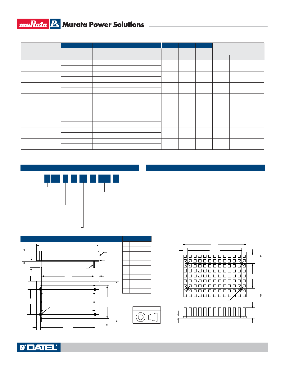
MECHANICAL SPECIFICATIONS
As shown below, TMP Model DC/DC Converters are classied by output
power. For triple-output devices, the sum of the output power from the primary
+5V output and the two auxiliary (±12V or ±15V) outputs can not exceed the
rated power. For example, "D24" models have a maximum power of 35W.
Therefore, if you source the maximum primary current of 5A, the devices will
only be able to provide 10W of total power from their auxilliary outputs.
75
100
75
100
75
100
75
100
75
100
75
100
75
100
75
120
84%
85%
86%
85%
86%
85%
Ripple/Noise (R/N) measured over a 20MHz bandwidth.
10-100% load on the primary +5V output, 20-100% balanced loads on the auxiliary outputs.
Nominal line voltage, no-load/full-load conditions.
OUTPUT POWER CONSIDERATIONS
2.600
(66.04)
0.20
(5.08)
2.00
(50.80)
1.200
(30.48)
3.00
(76.20)
0.50
(12.70)
0.40
(10.16)
0.10
(2.54)
0.120 DIA. (3.048)
(4 PLACES)
MATERIAL: BLACK ANODIZED ALUMINUM
4 MOUNTING SCREWS AND 0.009 (0.229) THERMAL PAD INCLUDED
TOP VIEW
Optional Heat Sink Kit (Part Number HS-23 <non-RoHS> or HS-23-C <RoHS>)
BOTTOM VIEW
2.500
(63.50)
0.27
(6.86)
7
6
8
9
4
1
2
0.22
(5.59)
1.200
(30.48)
2.600
(66.04)
0.42
(10.67)
3.04
(77.22)
(4) THREADED INSERTS
#4-40 THD THRU
0.22
(5.59)
3
5
10
0.55
(13.97)
0.20 MIN.
(5.08)
0.040 ±0.002 DIA.
(1.016 ±0.051)
INSULATED
BASE
METAL
CASE
1.600
(40.64)
4 EQ. SP. @
0.400 (10.16)
2.04
(51.82)
Case C11
- C
RoHS Compliant
Some model number combinations may
not be available. Please contact Murata
Power Solutions.
Third Angle Projection
Dimensions are in inches (mm shown for ref. only).
Components are shown for reference only.
Tolerances (unless otherwise specied):
.XX ± 0.02 (0.5)
.XXX ± 0.010 (0.25)
Angles ± 2
TMP Models
Triple Output, High-Efciency, Smaller-Package, 25-40 Watt, DC/DC Converters
Technical enquiries email: sales@murata-ps.com, tel: +1 508 339 3000
www.murata-ps.com
MDC_TMP25-40W_B02 Page 2 of 6
相关PDF资料 |
PDF描述 |
|---|---|
| TMP-5/5-12/1-D48-C | 3-OUTPUT 40 W DC-DC REG PWR SUPPLY MODULE |
| TMP-5/5-15/1-D24-C | 3-OUTPUT 35 W DC-DC REG PWR SUPPLY MODULE |
| TMR3-4810WI | 1-OUTPUT DC-DC REG PWR SUPPLY MODULE |
| TMR3-4811WI | 1-OUTPUT DC-DC REG PWR SUPPLY MODULE |
| TMR3-1223WI | 2-OUTPUT DC-DC REG PWR SUPPLY MODULE |
相关代理商/技术参数 |
参数描述 |
|---|---|
| TMP55-D23 | 制造商:TRUMPOWER 制造商全称:Tumbler Technologies + TRUMPower 功能描述:55 WATT MEDICAL POWER ADAPTERS |
| TMP55-D24 | 制造商:TRUMPOWER 制造商全称:Tumbler Technologies + TRUMPower 功能描述:55 WATT MEDICAL POWER ADAPTERS |
| TMP55-D25 | 制造商:TRUMPOWER 制造商全称:Tumbler Technologies + TRUMPower 功能描述:55 WATT MEDICAL POWER ADAPTERS |
| TMP55-S05 | 制造商:TRUMPOWER 制造商全称:Tumbler Technologies + TRUMPower 功能描述:55 WATT MEDICAL POWER ADAPTERS |
| TMP55-S06 | 制造商:TRUMPOWER 制造商全称:Tumbler Technologies + TRUMPower 功能描述:55 WATT MEDICAL POWER ADAPTERS |
发布紧急采购,3分钟左右您将得到回复。