- 您现在的位置:买卖IC网 > Datasheet目录47 > TMP401AIDGKTG4 (Texas Instruments)IC TEMP SENSOR DGTL OUT 8-MSOP Datasheet资料下载
参数资料
| 型号: | TMP401AIDGKTG4 |
| 厂商: | Texas Instruments |
| 文件页数: | 8/28页 |
| 文件大小: | 881K |
| 描述: | IC TEMP SENSOR DGTL OUT 8-MSOP |
| 标准包装: | 250 |
| 功能: | 温度监控系统(传感器) |
| 传感器类型: | 内部和外部 |
| 感应温度: | -40°C ~ 125°C |
| 精确度: | ±3°C 本地(最大),±5°C 远程(最大) |
| 拓扑: | ADC,比较器,寄存器库 |
| 输出类型: | 2 线 SMBus? |
| 输出警报: | 是 |
| 输出风扇: | 是 |
| 电源电压: | 3 V ~ 5.5 V |
| 工作温度: | -40°C ~ 125°C |
| 安装类型: | 表面贴装 |
| 封装/外壳: | 8-TSSOP,8-MSOP(0.118",3.00mm 宽) |
| 供应商设备封装: | 8-MSOP |
| 包装: | 带卷 (TR) |
第1页第2页第3页第4页第5页第6页第7页当前第8页第9页第10页第11页第12页第13页第14页第15页第16页第17页第18页第19页第20页第21页第22页第23页第24页第25页第26页第27页第28页
TMP401
SBOS371A AUGUST 2006 REVISED OCTOBER 2007
www.ti.com
8
Table 2. Decimal Fraction Temperature Data Format (Local and Remote Temperature Low Bytes)
REMOTE
TEMPERATURE
REGISTER
LOW BYTE VALUE
LOCAL
TEMPERATURE
REGISTER
LOW BYTE VALUE
0.06255C RESOLUTION
0.55C RESOLUTION
0.255C RESOLUTION
0.1255C RESOLUTION
0.06255C RESOLUTION
TEMP
(5C)
STANDARD
AND
EXTENDED
BINARY
HEX
STANDARD
AND
EXTENDED
BINARY
HEX
STANDARD
AND
EXTENDED
BINARY
HEX
STANDARD
AND
EXTENDED
BINARY
HEX
STANDARD
AND
EXTENDED
BINARY
HEX
0.0000
0000 0000
00
0000 0000
00
0000 0000
00
0000 0000
00
0000 0000
00
0.0625
0001 0000
10
0000 0000
00
0000 0000
00
0000 0000
00
0001 0000
10
0.1250
0010 0000
20
0000 0000
00
0000 0000
00
0010 0000
20
0010 0000
20
0.1875
0011 0000
30
0000 0000
00
0000 0000
00
0010 0000
20
0011 0000
30
0.2500
0100 0000
40
0000 0000
00
0100 0000
40
0100 0000
40
0100 0000
40
0.3125
0101 0000
50
0000 0000
00
0100 0000
40
0100 0000
40
0101 0000
50
0.3750
0110 0000
60
0000 0000
00
0100 0000
40
0110 0000
60
0110 0000
60
0.4375
0111 0000
70
0000 0000
00
0100 0000
40
0110 0000
60
0111 0000
70
0.5000
1000 0000
80
1000 0000
80
1000 0000
80
1000 0000
80
1000 0000
80
0.5625
1001 0000
90
1000 0000
80
1000 0000
80
1000 0000
80
1001 0000
90
0.6250
1010 0000
A0
1000 0000
80
1000 0000
80
1010 0000
A0
1010 0000
A0
0.6875
1011 0000
B0
1000 0000
80
1000 0000
80
1010 0000
A0
1011 0000
B0
0.7500
1100 0000
C0
1000 0000
80
1100 0000
C0
1100 0000
C0
1100 0000
C0
0.8125
1101 0000
D0
1000 0000
80
1100 0000
C0
1100 0000
C0
1101 0000
D0
0.8750
1110 0000
E0
1000 0000
80
1100 0000
C0
1110 0000
E0
1110 0000
E0
0.9375
1111 0000
F0
1000 0000
80
1100 0000
C0
1110 0000
E0
1111 0000
F0
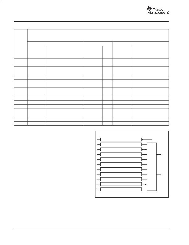
REGISTER INFORMATION
The TMP401 contains multiple registers for holding
configuration information, temperature measurement
results, temperature comparator limits, and status
information. These registers are described in Figure 12
and Table 3.
POINTER REGISTER
Figure 12 shows the internal register structure of the
TMP401. The 8-bit Pointer Register is used to address a
given data register. The Pointer Register identifies which
of the data registers should respond to a read or write
command on the Two-Wire bus. This register is set with
every write command. A write command must be issued
to set the proper value in the Pointer Register before
executing a read command. Table 3 describes the pointer
address of the registers available in the TMP401. The
power-on reset (POR) value of the Pointer Register is 00h
(0000 0000b).
Hysteresis Register
Resolution Register
Configuration Register
Status Register
Consecutive Alert Register
OneShot Register
Identification Registers
Conversion Rate Register
Local and Remote Limit Registers
Local and Remote Temperature Registers
SDA
SCL
Pointer Register
I/O
Control
Interface
Figure 12. Internal Register Structure
相关PDF资料 |
PDF描述 |
|---|---|
| TPS2346PWRG4 | IC HOT SWAP POWER MGR 24-TSSOP |
| TPS24711DGSR | IC CTRLR HOT SWAP 2.5-18V 10MSOP |
| TPS2491DGSG4 | IC POS HV HOT-SWAP CTRLR 10-MSOP |
| W83772G | IC H/W MONITOR 8-TSSOP |
| W83L786G | IC H/W MONITOR 28-SSOP |
相关代理商/技术参数 |
参数描述 |
|---|---|
| TMP411 | 制造商:BB 制造商全称:BB 功能描述:【1C Remote and Local TEMPERATURE SENSOR with N-Factor and Series Resistance Correction |
| TMP411_07 | 制造商:BB 制造商全称:BB 功能描述:【1∑C Remote and Local TEMPERATURE SENSOR with N-Factor and Series Resistance Correction |
| TMP411_13 | 制造商:TI 制造商全称:Texas Instruments 功能描述:?±1?°C Remote and Local TEMPERATURE SENSOR with N-Factor and Series Resistance Correction |
| TMP411A | 制造商:BB 制造商全称:BB 功能描述:【1∑C Remote and Local TEMPERATURE SENSOR with N-Factor and Series Resistance Correction |
| TMP411AD | 功能描述:板上安装温度传感器 +/-1degC Remote and Local Temp SENSOR RoHS:否 制造商:Omron Electronics 输出类型:Digital 配置: 准确性:+/- 1.5 C, +/- 3 C 温度阈值: 数字输出 - 总线接口:2-Wire, I2C, SMBus 电源电压-最大:5.5 V 电源电压-最小:4.5 V 最大工作温度:+ 50 C 最小工作温度:0 C 关闭: 安装风格: 封装 / 箱体: 设备功能:Temperature and Humidity Sensor |
发布紧急采购,3分钟左右您将得到回复。