- 您现在的位置:买卖IC网 > PDF目录382635 > TMS320C6454GTZ (Texas Instruments, Inc.) Fixed-Point Digital Signal Processor PDF资料下载
参数资料
| 型号: | TMS320C6454GTZ |
| 厂商: | Texas Instruments, Inc. |
| 元件分类: | 数字信号处理 |
| 英文描述: | Fixed-Point Digital Signal Processor |
| 中文描述: | 定点数字信号处理器 |
| 文件页数: | 28/225页 |
| 文件大小: | 1663K |
| 代理商: | TMS320C6454GTZ |
第1页第2页第3页第4页第5页第6页第7页第8页第9页第10页第11页第12页第13页第14页第15页第16页第17页第18页第19页第20页第21页第22页第23页第24页第25页第26页第27页当前第28页第29页第30页第31页第32页第33页第34页第35页第36页第37页第38页第39页第40页第41页第42页第43页第44页第45页第46页第47页第48页第49页第50页第51页第52页第53页第54页第55页第56页第57页第58页第59页第60页第61页第62页第63页第64页第65页第66页第67页第68页第69页第70页第71页第72页第73页第74页第75页第76页第77页第78页第79页第80页第81页第82页第83页第84页第85页第86页第87页第88页第89页第90页第91页第92页第93页第94页第95页第96页第97页第98页第99页第100页第101页第102页第103页第104页第105页第106页第107页第108页第109页第110页第111页第112页第113页第114页第115页第116页第117页第118页第119页第120页第121页第122页第123页第124页第125页第126页第127页第128页第129页第130页第131页第132页第133页第134页第135页第136页第137页第138页第139页第140页第141页第142页第143页第144页第145页第146页第147页第148页第149页第150页第151页第152页第153页第154页第155页第156页第157页第158页第159页第160页第161页第162页第163页第164页第165页第166页第167页第168页第169页第170页第171页第172页第173页第174页第175页第176页第177页第178页第179页第180页第181页第182页第183页第184页第185页第186页第187页第188页第189页第190页第191页第192页第193页第194页第195页第196页第197页第198页第199页第200页第201页第202页第203页第204页第205页第206页第207页第208页第209页第210页第211页第212页第213页第214页第215页第216页第217页第218页第219页第220页第221页第222页第223页第224页第225页
www.ti.com
P
TMS320C6454
Fixed-Point Digital Signal Processor
SPRS311A–APRIL 2006–REVISED DECEMBER 2006
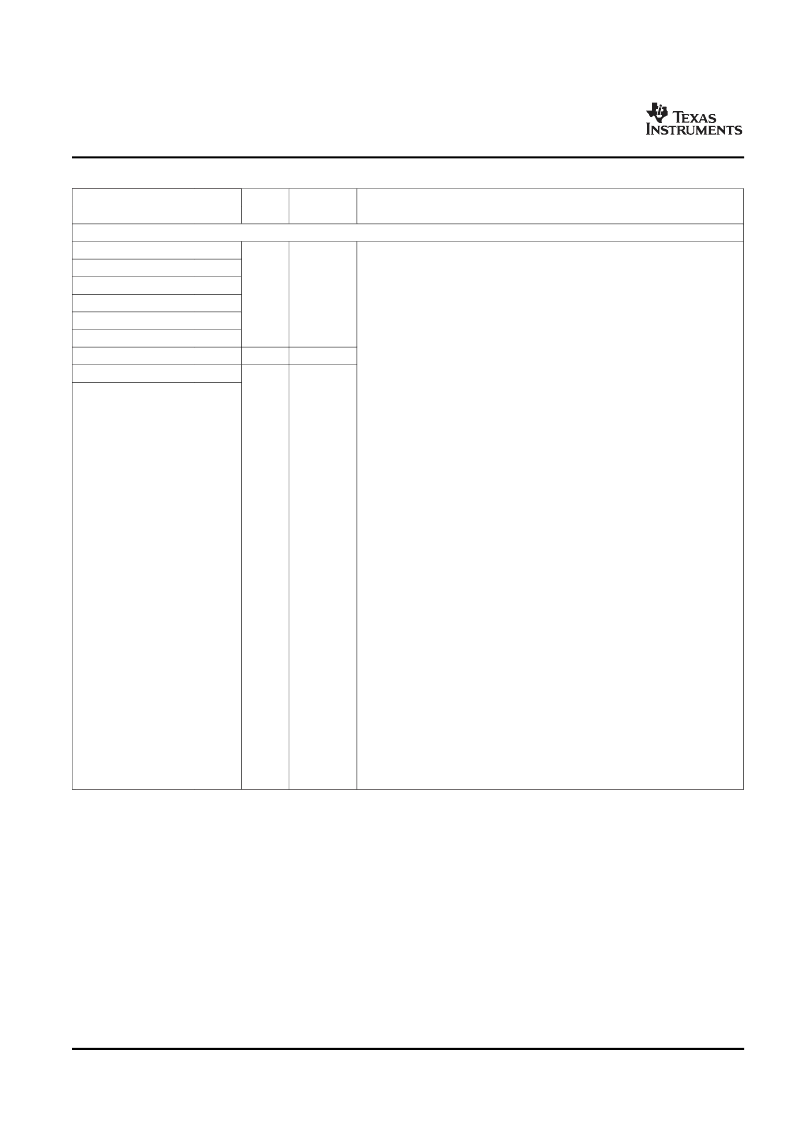
Table 2-3. Terminal Functions (continued)
SIGNAL
NAME
TYPE
(1)
IPD/IPU
(2)
DESCRIPTION
NO.
EMIFA (64-BIT) - ADDRESS
EMIFA external address (word address) (
O/Z
)
Controls initialization of the DSP modes at reset (
I
) via pullup/pulldown resistors
[For more detailed information, see
Section 3
,
Device Configuration
.]
Note:
If a configuration pin must be routed out from the device, the internal
pullup/pulldown (IPU/IPD) resistor should not be relied upon; TI recommends
the use of an external pullup/pulldown resistor.
AEA19/BOOTMODE3
AEA18/BOOTMODE2
AEA17/BOOTMODE1
AEA16/BOOTMODE0
AEA15/AECLKIN_SEL
AEA14/HPI_WIDTH
AEA13/LENDIAN
AEA12
N25
L26
L25
P26
P27
R25
R27
R28
O/Z
IPD
Boot mode - device boot mode configurations (BOOTMODE[3:0]) [
Note:
the peripheral
must
be enabled to use the particular boot mode.]
AEA[19:16]
:
0000 - No boot (default mode)
0001 - Host boot (HPI)
0010 -Reserved
0011 - Reserved
0100 - EMIFA 8-bit ROM boot
0101 - Master I2C boot
0110 - Slave I2C boot
0111 - Host boot (PCI)
1000 thru 1111 - Reserved
For more detailed information on the boot modes, see
Section 2.4
,
Boot
Sequence
.
CFGGP[2:0] pins must be set to 000b during reset for proper operation of
the PCI boot mode.
EMIFA input clock source select
Clock mode select for EMIFA (AECLKIN_SEL)
AEA15
:
0 - AECLKIN (default mode)
1 - SYSCLK4 (CPU/x) Clock Rate. The SYSCLK4 clock rate is software
selectable via the Software PLL1 Controller. By default, SYSCLK4 is
selected as CPU/8 clock rate.
HPI peripheral bus width (HPI_WIDTH) select
[Applies only when HPI is enabled; PCI_EN pin = 0]
AEA14
:
0 - HPI operates as an HPI16 (default). (HPI bus is 16 bits wide. HD[15:0]
pins are used and the remaining HD[31:16] pins are reserved pins in the
Hi-Z state.)
1 - HPI operates as an HPI32.
Device Endian mode (LENDIAN)
AEA13
:
0 - System operates in Big Endian mode
1 - System operates in Little Endian mode(default)
O/Z
IPU
O/Z
IPD
AEA11
T25
Note:
For proper C6454 device operation, the
AEA12
and
AEA11
pins
must
be externally pulled down with a 1-k
resistor at device reset.
Device Overview
28
Submit Documentation Feedback
相关PDF资料 |
PDF描述 |
|---|---|
| TMS320C6454GTZ8 | Fixed-Point Digital Signal Processor |
| TMS320C6454ZTZ | Fixed-Point Digital Signal Processor |
| TMS320C6454ZTZ7 | Fixed-Point Digital Signal Processor |
| TMS320C6454ZTZ8 | Fixed-Point Digital Signal Processor |
| TMX320C6454GTZ | Fixed-Point Digital Signal Processor |
相关代理商/技术参数 |
参数描述 |
|---|---|
| TMS320C6454GTZ7 | 制造商:TI 制造商全称:Texas Instruments 功能描述:Fixed-Point Digital Signal Processor |
| TMS320C6454GTZ8 | 制造商:TI 制造商全称:Texas Instruments 功能描述:Fixed-Point Digital Signal Processor |
| TMS320C6454ZTZ | 制造商:TI 制造商全称:Texas Instruments 功能描述:Fixed-Point Digital Signal Processor |
| TMS320C6454ZTZ7 | 制造商:TI 制造商全称:Texas Instruments 功能描述:Fixed-Point Digital Signal Processor |
| TMS320C6454ZTZ8 | 制造商:TI 制造商全称:Texas Instruments 功能描述:Fixed-Point Digital Signal Processor |
发布紧急采购,3分钟左右您将得到回复。