- 您现在的位置:买卖IC网 > PDF目录97229 > TMXW520 (TEMEX COMPONENTS) 1 FUNCTIONS, 456 MHz, SAW FILTER PDF资料下载
参数资料
| 型号: | TMXW520 |
| 厂商: | TEMEX COMPONENTS |
| 元件分类: | 声表面波滤波器 |
| 英文描述: | 1 FUNCTIONS, 456 MHz, SAW FILTER |
| 封装: | ROHS COMPLIANT, CERAMIC PACKAGE-10 |
| 文件页数: | 3/6页 |
| 文件大小: | 444K |
| 代理商: | TMXW520 |
TMX W520
SAW Bandpass Filter – WiMax – IF
Preliminary Specification (Rev 3)
October 02nd, 2006
TEMEX reserves the right to modify herein specifications and informations at any time when necessary to provide optimum performance and cost.
2
Technical Characteristics
Operating Temperature range : [-40°C ; +85°C]
Electrical Parameters
Unit
Minimum
Typical (1)
Maximum
Source Impedance (single ended)
-
200 (2)
-
Load Impedance (single ended)
-
200 (2)
-
Center Frequency fo
MHz
-
456
-
Bandwidth at –3 dB (3)
MHz
3.7
4.3
-
Template on the amplitude, amplitude reference is minimum insertion loss
From 1 MHz to 256 MHz
dB
30
65
-
From 256 MHz to 360 MHz
dB
40
60
-
From 360 MHz to 416 MHz
dB
50
57
-
From 416 MHz to 452.65 MHz
dB
40
45
-
From 459.35 MHz to 656 MHz
dB
40
45
-
From 656 MHz to 946 MHz
dB
30
45
-
Minimum Insertion Loss over 3.7 MHz Bw(2)
dB
-
9.5
10.5
Amplitude Variation
in fo ±
±±± 1.7 MHz (4)
in fo ± 1.85 MHz (4)
dBp-p
-
0.8
1.3
1.2
3.0
Group Delay Variation in fo ± 1.7 MHz
nsp-p
-
140
300
Absolute Group Delay at fo
s
-
0.58
3.0
Input Return Loss in fo ±
±±± 1.7 MHz
dB
6.0
11
-
Output Return Loss in fo ±
±±± 1.7 MHz
dB
6.0
14
-
Impulse Response Attenuation (5)
1 - 2 s
2 - 3 s
> 3 s
dB
20
30
45
35
40
55
-
Notes :
(1) Typical values are nominal performances at room temperature.
(2) With external matching networks.
(3) The amplitude reference is minimum insertion loss over 3.7 MHz bandwidth.
(4) The amplitude variation is defined as the maximum level – minimum level over the given bandwidth.
(5) Time reference is the main time response lobe
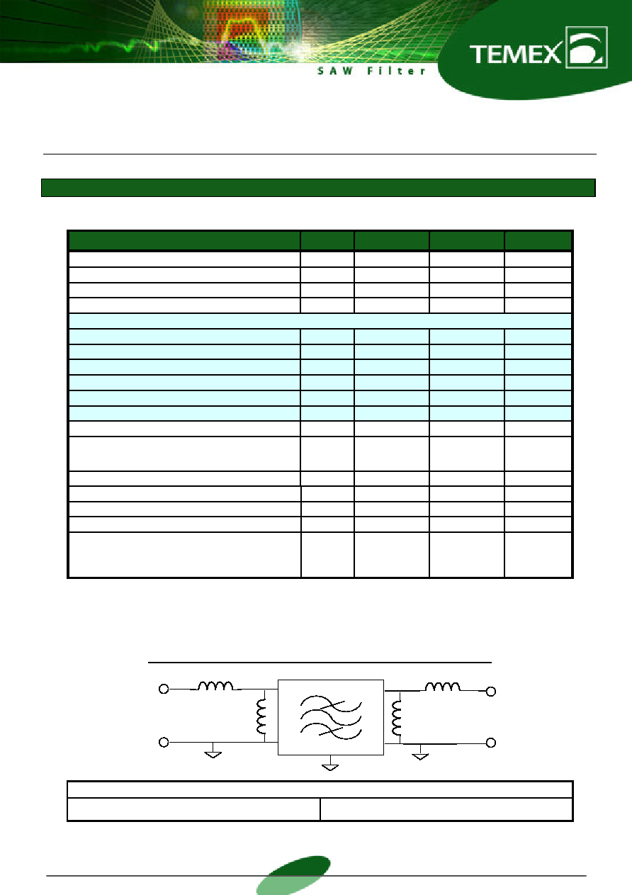
MATCHING NETWORK FOR 200
SINGLE ENDED CONFIGURATION
Temex Test Fixture
L1 = 120 nH ,Q>35
L2 = 36 nH ; Q > 60
L3 = 36 nH ,Q>60
L4 = 110 nH; Q > 35
The configuration is given for indication only . The components values may be different on the customer PC board.
Input
200
Single ended
Output
200
Single ended
L1
1
6
10
5
L2
L4
L3
GND
相关PDF资料 |
PDF描述 |
|---|---|
| TMXW602 | 1 FUNCTIONS, 199 MHz, SAW FILTER |
| TMXW603 | 1 FUNCTIONS, 211 MHz, SAW FILTER |
| TMXW604 | 1 FUNCTIONS, 238.5 MHz, SAW FILTER |
| TMXW607 | 1 FUNCTIONS, 150 MHz, SAW FILTER |
| TMXW610 | 1 FUNCTIONS, 199 MHz, SAW FILTER |
相关代理商/技术参数 |
参数描述 |
|---|---|
| TMY320DA150PGE120 | 制造商:Texas Instruments 功能描述: |
| TMYBKN_Z08TNS WAF | 制造商:Fairchild Semiconductor Corporation 功能描述: |
| TMZ2AX5003 | 制造商:Panasonic Industrial Company 功能描述:BRACKET |
| TMZ2AX5004 | 制造商:Panasonic Industrial Company 功能描述:BRACKET |
| TMZ626802-12DGE | 制造商:Rochester Electronics LLC 功能描述:- Bulk 制造商:Texas Instruments 功能描述: |
发布紧急采购,3分钟左右您将得到回复。