- 您现在的位置:买卖IC网 > PDF目录97229 > TMXW602 (TEMEX COMPONENTS) 1 FUNCTIONS, 199 MHz, SAW FILTER PDF资料下载
参数资料
| 型号: | TMXW602 |
| 厂商: | TEMEX COMPONENTS |
| 元件分类: | 声表面波滤波器 |
| 英文描述: | 1 FUNCTIONS, 199 MHz, SAW FILTER |
| 文件页数: | 2/4页 |
| 文件大小: | 369K |
| 代理商: | TMXW602 |
TMX W602
SAW BandPASS Filter - BASE STATION GSM - Rx IF
Preliminary Specification (Rev-)
May 30
th, 2005
1
TEMEX reserves the right to modify herein specifications and informations at any time when necessary to provide optimum performance and cost.
Operating temperature range : [-35°C; +85°C]
Electrical Parameters
(1)
Unit
Minimum
Typical
(2)
Maximum
Source Impedance (balanced)
-
400
(3)
-
Load Impedance (balanced)
-
200
(3)
-
Center Frequency fo
MHz
-
199
-
Bandwidth at –1 dB
kHz
± 100
± 240
-
Template on the amplitude, reference is insertion loss at fo
From fo - 80 MHz to fo - 30 MHz
dB
35
40
-
From fo - 30 MHz to fo - 800 kHz
dB
30
35
-
From fo - 800 kHz to fo - 600 kHz
dB
20
25
-
From fo + 600 kHz to fo + 800 kHz
dB
20
25
-
From fo + 800 kHz to fo + 17 MHz
dB
30
35
-
From fo + 17 MHz to fo + 80 MHz
dB
35
40
-
Insertion Loss at fo
dB
-
5.8
7.0
Amplitude Variation over fo
± 100 kHz (4)
dBp-p
-
0.25
0.5
Group Delay Variation over fo
± 100 kHz
nsp-p
-
130
500
Package type & size
SMD
Length x Width
mm
-
9.1 x 7.1
-
Height
mm
-
1.8
Pin Out
Input
1, 10
Output
5, 6
Case Ground
2, 3, 7, 8
To Be Grounded
2, 3, 4, 7, 8, 9
Notes :
(1)
All specifications apply on the TEMEX test fixture, including matching networks
(2)
Typical values are nominal performances at room temperature
(3)
50
single ended configuration also possible
(4)
The amplitude variation is defined as the maximum level – minimum level over the given bandwidth
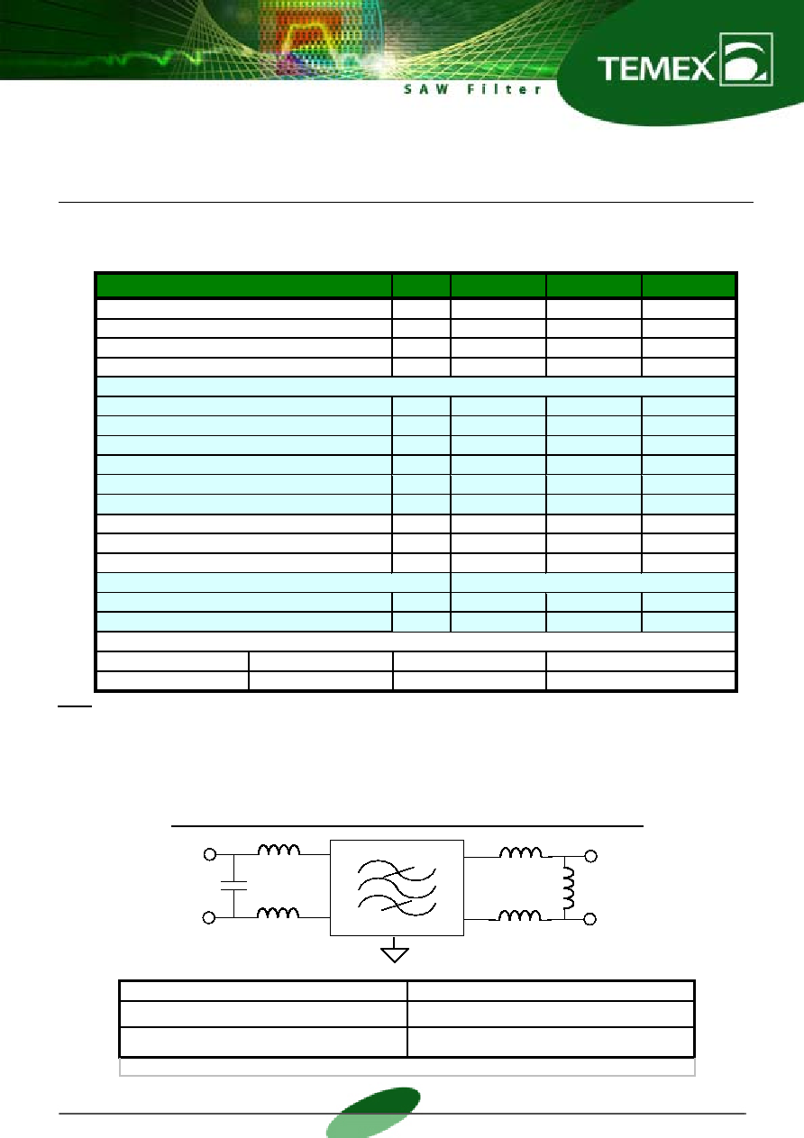
MATCHING NETWORK FOR 400
/ 200 BALANCED CONFIGURATION
C1
L3
L1
L2
GND
Output
200
Balanced
Input
400
Balanced
Temex Test Fixture
Customer PC Board
L1 = 82 nH; Q > 45
C1 = 1 pF
L1 = TBD ; Q > 45
C1 = TBD
L2 = 39 nH, Q > 45
L3 = 68 nH; Q > 45
L2 = TBD ,
L3 = TBD ; Q > 45
TBD = To Be Defined
相关PDF资料 |
PDF描述 |
|---|---|
| TMXW603 | 1 FUNCTIONS, 211 MHz, SAW FILTER |
| TMXW604 | 1 FUNCTIONS, 238.5 MHz, SAW FILTER |
| TMXW607 | 1 FUNCTIONS, 150 MHz, SAW FILTER |
| TMXW610 | 1 FUNCTIONS, 199 MHz, SAW FILTER |
| TMXW611 | 1 FUNCTIONS, 140 MHz, SAW FILTER |
相关代理商/技术参数 |
参数描述 |
|---|---|
| TMY320DA150PGE120 | 制造商:Texas Instruments 功能描述: |
| TMYBKN_Z08TNS WAF | 制造商:Fairchild Semiconductor Corporation 功能描述: |
| TMZ2AX5003 | 制造商:Panasonic Industrial Company 功能描述:BRACKET |
| TMZ2AX5004 | 制造商:Panasonic Industrial Company 功能描述:BRACKET |
| TMZ626802-12DGE | 制造商:Rochester Electronics LLC 功能描述:- Bulk 制造商:Texas Instruments 功能描述: |
发布紧急采购,3分钟左右您将得到回复。