- 您现在的位置:买卖IC网 > PDF目录17098 > TOOLSTICK502DC (Silicon Laboratories Inc)DAUGHTER CARD TOOLSTICK F500 PDF资料下载
参数资料
| 型号: | TOOLSTICK502DC |
| 厂商: | Silicon Laboratories Inc |
| 文件页数: | 266/312页 |
| 文件大小: | 0K |
| 描述: | DAUGHTER CARD TOOLSTICK F500 |
| 标准包装: | 1 |
| 系列: | ToolStick |
| 类型: | MCU |
| 适用于相关产品: | C8051F502 |
| 所含物品: | 板 |
| 配用: | 336-1345-ND - TOOLSTICK BASE ADAPTER 336-1182-ND - ADAPTER USB DEBUG FOR C8051FXXX |
| 相关产品: | 336-1515-5-ND - IC 8051 MCU 64K FLASH 32-QFN 336-1514-ND - IC 8051 MCU 64K FLASH 32-QFP |
| 其它名称: | 336-1528 TOOLSTICK500DC |
第1页第2页第3页第4页第5页第6页第7页第8页第9页第10页第11页第12页第13页第14页第15页第16页第17页第18页第19页第20页第21页第22页第23页第24页第25页第26页第27页第28页第29页第30页第31页第32页第33页第34页第35页第36页第37页第38页第39页第40页第41页第42页第43页第44页第45页第46页第47页第48页第49页第50页第51页第52页第53页第54页第55页第56页第57页第58页第59页第60页第61页第62页第63页第64页第65页第66页第67页第68页第69页第70页第71页第72页第73页第74页第75页第76页第77页第78页第79页第80页第81页第82页第83页第84页第85页第86页第87页第88页第89页第90页第91页第92页第93页第94页第95页第96页第97页第98页第99页第100页第101页第102页第103页第104页第105页第106页第107页第108页第109页第110页第111页第112页第113页第114页第115页第116页第117页第118页第119页第120页第121页第122页第123页第124页第125页第126页第127页第128页第129页第130页第131页第132页第133页第134页第135页第136页第137页第138页第139页第140页第141页第142页第143页第144页第145页第146页第147页第148页第149页第150页第151页第152页第153页第154页第155页第156页第157页第158页第159页第160页第161页第162页第163页第164页第165页第166页第167页第168页第169页第170页第171页第172页第173页第174页第175页第176页第177页第178页第179页第180页第181页第182页第183页第184页第185页第186页第187页第188页第189页第190页第191页第192页第193页第194页第195页第196页第197页第198页第199页第200页第201页第202页第203页第204页第205页第206页第207页第208页第209页第210页第211页第212页第213页第214页第215页第216页第217页第218页第219页第220页第221页第222页第223页第224页第225页第226页第227页第228页第229页第230页第231页第232页第233页第234页第235页第236页第237页第238页第239页第240页第241页第242页第243页第244页第245页第246页第247页第248页第249页第250页第251页第252页第253页第254页第255页第256页第257页第258页第259页第260页第261页第262页第263页第264页第265页当前第266页第267页第268页第269页第270页第271页第272页第273页第274页第275页第276页第277页第278页第279页第280页第281页第282页第283页第284页第285页第286页第287页第288页第289页第290页第291页第292页第293页第294页第295页第296页第297页第298页第299页第300页第301页第302页第303页第304页第305页第306页第307页第308页第309页第310页第311页第312页
Rev. 1.2
57
C8051F50x/F51x
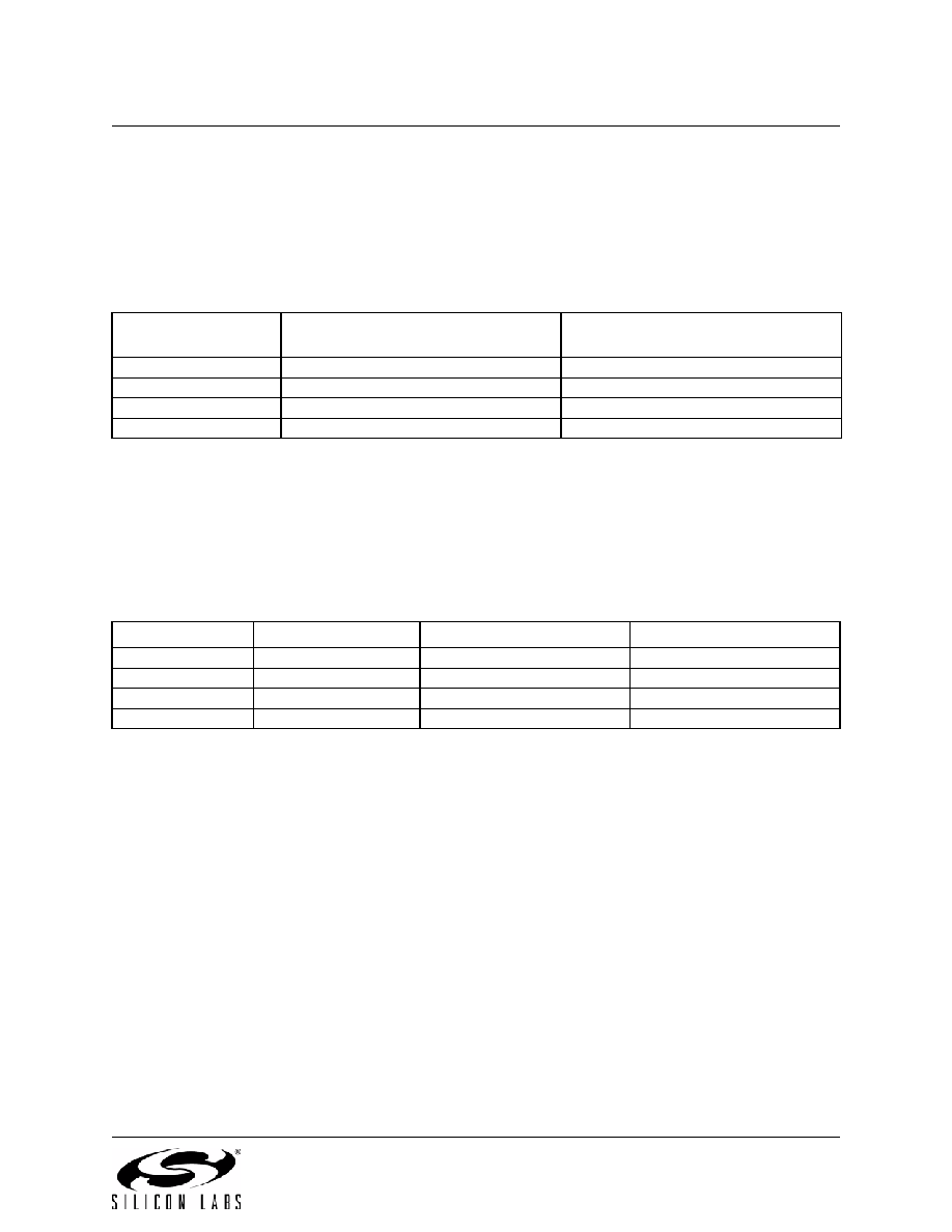
6.2. Output Code Formatting
The registers ADC0H and ADC0L contain the high and low bytes of the output conversion code. When the
repeat count is set to 1, conversion codes are represented in 12-bit unsigned integer format and the output
conversion code is updated after each conversion. Inputs are measured from 0 to VREF x 4095/4096. Data
can be right-justified or left-justified, depending on the setting of the AD0LJST bit (ADC0CN.2). Unused
bits in the ADC0H and ADC0L registers are set to 0. Example codes are shown below for both right-justi-
fied and left-justified data.
When the ADC0 Repeat Count is greater than 1, the output conversion code represents the accumulated
result of the conversions performed and is updated after the last conversion in the series is finished. Sets
of 4, 8, or 16 consecutive samples can be accumulated and represented in unsigned integer format. The
repeat count can be selected using the AD0RPT bits in the ADC0CF register. The value must be right-jus-
tified (AD0LJST = 0), and unused bits in the ADC0H and ADC0L registers are set to 0. The following
example shows right-justified codes for repeat counts greater than 1. Notice that accumulating 2n samples
is equivalent to left-shifting by n bit positions when all samples returned from the ADC have the same
value.
6.2.1. Settling Time Requirements
A minimum tracking time is required before an accurate conversion is performed. This tracking time is
determined by any series impedance, including the AMUX0 resistance, the ADC0 sampling capacitance,
and the accuracy required for the conversion.
Figure 6.5 shows the equivalent ADC0 input circuit. The required ADC0 settling time for a given settling
accuracy (SA) may be approximated by Equation 6.1. When measuring the Temperature Sensor output,
use the settling time specified in Table 5.10 on page 50. When measuring VDD with respect to GND, RTO-
impedance and sampling capacitor values.
Equation 6.1. ADC0 Settling Time Requirements
Where:
SA is the settling accuracy, given as a fraction of an LSB (for example, 0.25 to settle within 1/4 LSB)
t is the required settling time in seconds
RTOTAL is the sum of the AMUX0 resistance and any external source resistance.
n is the ADC resolution in bits (10).
Input Voltage
Right-Justified ADC0H:ADC0L
(AD0LJST = 0)
Left-Justified ADC0H:ADC0L
(AD0LJST = 1)
VREF x 4095/4096
0x0FFF
0xFFF0
VREF x 2048/4096
0x0800
0x8000
VREF x 2047/4096
0x07FF
0x7FF0
0
0x0000
Input Voltage
Repeat Count = 4
Repeat Count = 8
Repeat Count = 16
VREF x 4095/4096
0x3FFC
0x7FF8
0xFFF0
VREF x 2048/4096
0x2000
0x4000
0x8000
VREF x 2047/4096
0x1FFC
0x3FF8
0x7FF0
0
0x0000
t
2
n
SA
--------
R
TOTALCSAMPLE
ln
=
相关PDF资料 |
PDF描述 |
|---|---|
| 1-1546452-2 | CABLE PLUG-PLUG ETHERNET 5METER |
| SDR-RD | SCOTCH CODE REFILL RED |
| RMM08DRTH | CONN EDGECARD 16POS DIP .156 SLD |
| 1546453-2 | CABLE PLUG-PLUG ETHERNET 5 METER |
| 1546453-1 | CABLE PLUG-PLUG ETHERNET 2 METER |
相关代理商/技术参数 |
参数描述 |
|---|---|
| TOOLSTICK502MPP | 功能描述:插座和适配器 TSTICK PROGRAMER FOR C8051F50x(32QFN) RoHS:否 制造商:Silicon Labs 产品:Adapter 用于:EM35x |
| TOOLSTICK502QPP | 功能描述:插座和适配器 Tstick Programer for C8051F50x (32QFP) RoHS:否 制造商:Silicon Labs 产品:Adapter 用于:EM35x |
| TOOLSTICK520PP | 功能描述:插座和适配器 Dev Tool for C8051F520-F527 RoHS:否 制造商:Silicon Labs 产品:Adapter 用于:EM35x |
| TOOLSTICK530ADC | 功能描述:子卡和OEM板 C8051F52xA/53xA Daughter Card RoHS:否 制造商:BeagleBoard by CircuitCo 产品:BeagleBone LCD4 Boards 用于:BeagleBone - BB-Bone - Open Source Development Kit |
| TOOLSTICK530MPP | 功能描述:插座和适配器 C8051F530/1/3/4/6/7- IM MCUs Dev Tool RoHS:否 制造商:Silicon Labs 产品:Adapter 用于:EM35x |
发布紧急采购,3分钟左右您将得到回复。