- 您现在的位置:买卖IC网 > PDF目录69498 > TOP244PN-TL (POWER INTEGRATIONS INC) 2.16 A SWITCHING REGULATOR, 140 kHz SWITCHING FREQ-MAX, PDIP7 PDF资料下载
参数资料
| 型号: | TOP244PN-TL |
| 厂商: | POWER INTEGRATIONS INC |
| 元件分类: | 稳压器 |
| 英文描述: | 2.16 A SWITCHING REGULATOR, 140 kHz SWITCHING FREQ-MAX, PDIP7 |
| 封装: | PLASTIC, DIP-8/7 |
| 文件页数: | 49/52页 |
| 文件大小: | 457K |
| 代理商: | TOP244PN-TL |
第1页第2页第3页第4页第5页第6页第7页第8页第9页第10页第11页第12页第13页第14页第15页第16页第17页第18页第19页第20页第21页第22页第23页第24页第25页第26页第27页第28页第29页第30页第31页第32页第33页第34页第35页第36页第37页第38页第39页第40页第41页第42页第43页第44页第45页第46页第47页第48页当前第49页第50页第51页第52页
TOP242-250
6
H
9/02
General Information & Table of Contents
Product Selector Guide
1
Data Sheets
2
Application Notes
3
Design Ideas
4
Design Tools
5
Quality and Reliability
6
Package Information
7
DPA-Switch DC-DC Seminar
8
LinkSwitch & TinySwitch-II AC-DC Seminar
9
TOPSwitch-GX AC-DC Seminar 10
Sales Representatives and Distributors 11
PI-2545-082299
S1
S2
S6
S7
S1
S2
S6
S7
S0
S1
S7
S0
5.8 V
4.8 V
S7
0 V
V
LINE
V
C
V
DRAIN
V
OUT
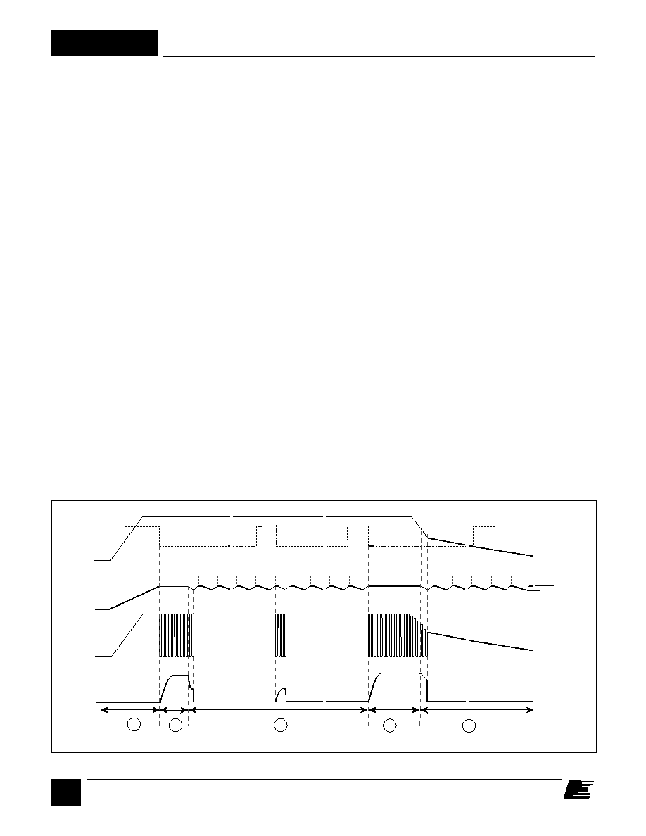
Note: S0 through S7 are the output states of the auto-restart counter
2
1
2
3
4
0 V
~ ~
S6
S7
~ ~
V
UV
~ ~
S2~~
CONTROL (C) Pin Operation
The CONTROL pin is a low impedance node that is capable of
receiving a combined supply and feedback current. During
normal operation, a shunt regulator is used to separate the feed-
back signal from the supply current. CONTROL pin voltage
V
C is the supply voltage for the control circuitry including the
MOSFET gate driver. An external bypass capacitor closely
connected between the CONTROL and SOURCE pins is
required to supply the instantaneous gate drive current. The
total amount of capacitance connected to this pin also sets the
auto-restart timing as well as control loop compensation.
When rectified DC high voltage is applied to the DRAIN pin
during start-up, the MOSFET is initially off, and the
CONTROL pin capacitor is charged through a switched high
voltage current source connected internally between the DRAIN
and CONTROL pins. When the CONTROL pin voltage V
C
reaches approximately 5.8 V, the control circuitry is activated
and the soft-start begins. The soft-start circuit gradually
increases the duty cycle of the MOSFET from zero to the maxi-
mum value over approximately 10 ms. If no external feedback/
supply current is fed into the CONTROL pin by the end of the
soft-start, the high voltage current source is turned off and the
CONTROL pin will start discharging in response to the supply
current drawn by the control circuitry. If the power supply is
designed properly, and no fault condition such as open loop or
shorted output exists, the feedback loop will close, providing
external CONTROL pin current, before the CONTROL pin
voltage has had a chance to discharge to the lower threshold
voltage of approximately 4.8 V (internal supply under-voltage
lockout threshold). When the externally fed current charges
the CONTROL pin to the shunt regulator voltage of 5.8 V, cur-
rent in excess of the consumption of the chip is shunted to
SOURCE through resistor R
E as shown in Figure 2.
This
current flowing through R
E controls the duty cycle of the power
MOSFET to provide closed loop regulation. The shunt
regulator has a finite low output impedance Z
C that sets the
gain of the error amplifier when used in a primary feedback
configuration. The dynamic impedance Z
C of the CONTROL
pin together with the external CONTROL pin capacitance sets
the dominant pole for the control loop.
When a fault condition such as an open loop or shorted output
prevents the flow of an external current into the CONTROL
pin, the capacitor on the CONTROL pin discharges towards
4.8 V. At 4.8 V, auto-restart is activated which turns the output
MOSFET off and puts the control circuitry in a low current
standby mode. The high-voltage current source turns on and
charges the external capacitance again. A hysteretic internal
supply under-voltage comparator keeps V
C within a window
of typically 4.8 V to 5.8 V by turning the high-voltage current
source on and off as shown in Figure 8. The auto-restart
circuit has a divide-by-eight counter which prevents the out-
put MOSFET from turning on again until eight discharge/charge
cycles have elapsed. This is accomplished by enabling the
output MOSFET only when the divide-by-eight counter reaches
full count (S7). The counter effectively limits TOPSwitch-GX
power dissipation by reducing the auto-restart duty cycle to
typically 4%. Auto-restart mode continues until output
voltage regulation is again achieved through closure of the
feedback loop.
Oscillator and Switching Frequency
The internal oscillator linearly charges and discharges an
internal capacitance between two voltage levels to create a
sawtooth waveform for the pulse width modulator. This
Figure 8. Typical Waveforms for (1) Power Up (2) Normal Operation (3) Auto-restart (4) Power Down.
相关PDF资料 |
PDF描述 |
|---|---|
| TOP250YN-TL | 10.08 A SWITCHING REGULATOR, 140 kHz SWITCHING FREQ-MAX, PZFM6 |
| TOP244RN-TL | 2.16 A SWITCHING REGULATOR, 140 kHz SWITCHING FREQ-MAX, PSSO6 |
| TOP244Y-TL | 2.16 A SWITCHING REGULATOR, 140 kHz SWITCHING FREQ-MAX, PZFM6 |
| TOP246Y-TL | 4.32 A SWITCHING REGULATOR, 140 kHz SWITCHING FREQ-MAX, PZFM6 |
| TOP245YN-TL | 2.88 A SWITCHING REGULATOR, 140 kHz SWITCHING FREQ-MAX, PZFM6 |
相关代理商/技术参数 |
参数描述 |
|---|---|
| TOP244P-TL | 制造商:POWERINT 制造商全称:Power Integrations, Inc. 功能描述:TOPSwitch-GX Family Extended Power, Design Flexible, EcoSmart, Integrated Off-line Switcher |
| TOP244R | 制造商:POWERINT 制造商全称:Power Integrations, Inc. 功能描述:TOPSwitch-GX Family Extended Power, Design Flexible, EcoSmart, Integrated Off-line Switcher |
| TOP244R- | 制造商:POWERINT 制造商全称:Power Integrations, Inc. 功能描述:TOPSwitch-GX Family Extended Power, Design Flexible, EcoSmart, Integrated Off-line Switcher |
| TOP244RN- | 制造商:POWERINT 制造商全称:Power Integrations, Inc. 功能描述:TOPSwitch-GX Family Extended Power, Design Flexible, EcoSmart, Integrated Off-line Switcher |
| TOP244RN-TL | 制造商:POWERINT 制造商全称:Power Integrations, Inc. 功能描述:TOPSwitch-GX Family Extended Power, Design Flexible, EcoSmart, Integrated Off-line Switcher |
发布紧急采购,3分钟左右您将得到回复。