- 您现在的位置:买卖IC网 > PDF目录98271 > TPA2017D2RTJT (TEXAS INSTRUMENTS INC) 2.8 W, 2 CHANNEL, AUDIO AMPLIFIER, PQCC20 PDF资料下载
参数资料
| 型号: | TPA2017D2RTJT |
| 厂商: | TEXAS INSTRUMENTS INC |
| 元件分类: | 音频/视频放大 |
| 英文描述: | 2.8 W, 2 CHANNEL, AUDIO AMPLIFIER, PQCC20 |
| 封装: | 4 X 4 MM, GREEN, PLASTIC, QFN-20 |
| 文件页数: | 4/20页 |
| 文件大小: | 642K |
| 代理商: | TPA2017D2RTJT |
DECOUPLING CAPACITOR (CS)
INPUT CAPACITORS (CI)
C
I
1
f =
(2
R
C )
p
(1)
I
C
1
C =
(2
R
f )
p
(2)
COMPONENT LOCATION
EFFICIENCY AND THERMAL INFORMATION
100°C/W
(3)
JA
DMAX
T
P
C
A
J
Max =
Max -
= 150 - 100 (0.4) = 110
q
°
(4)
OPERATION WITH DACS AND CODECS
SLOS584 – APRIL 2009 ..................................................................................................................................................................................................... www.ti.com
The TPA2017D2 is a high-performance Class-D audio amplifier that requires adequate power supply decoupling
to ensure the efficiency is high and total harmonic distortion (THD) is low. For higher frequency transients,
spikes, or digital hash on the line, a good low equivalent-series-resistance (ESR) 1-
F ceramic capacitor
(typically) placed as close as possible to the device PVDD (L, R) lead works best. Placing this decoupling
capacitor close to the TPA2017D2 is important for the efficiency of the Class-D amplifier, because any resistance
or inductance in the trace between the device and the capacitor can cause a loss in efficiency. For filtering
lower-frequency noise signals, a 4.7
F or greater capacitor placed near the audio power amplifier would also
help, but it is not required in most applications because of the high PSRR of this device.
The input capacitors and input resistors form a high-pass filter with the corner frequency, fC, determined in
The value of the input capacitor is important to consider as it directly affects the bass (low frequency)
performance of the circuit. Speakers in wireless phones cannot usually respond well to low frequencies, so the
corner frequency can be set to block low frequencies in this application. Not using input capacitors can increase
output offset. Equation 2 is used to solve for the input coupling capacitance. If the corner frequency is within the
audio band, the capacitors should have a tolerance of ±10% or better, because any mismatch in capacitance
causes an impedance mismatch at the corner frequency and below.
Place all the external components very close to the TPA2017D2. Placing the decoupling capacitor, CS, close to
the TPA2017D2 is important for the efficiency of the Class-D amplifier. Any resistance or inductance in the trace
between the device and the capacitor can cause a loss in efficiency.
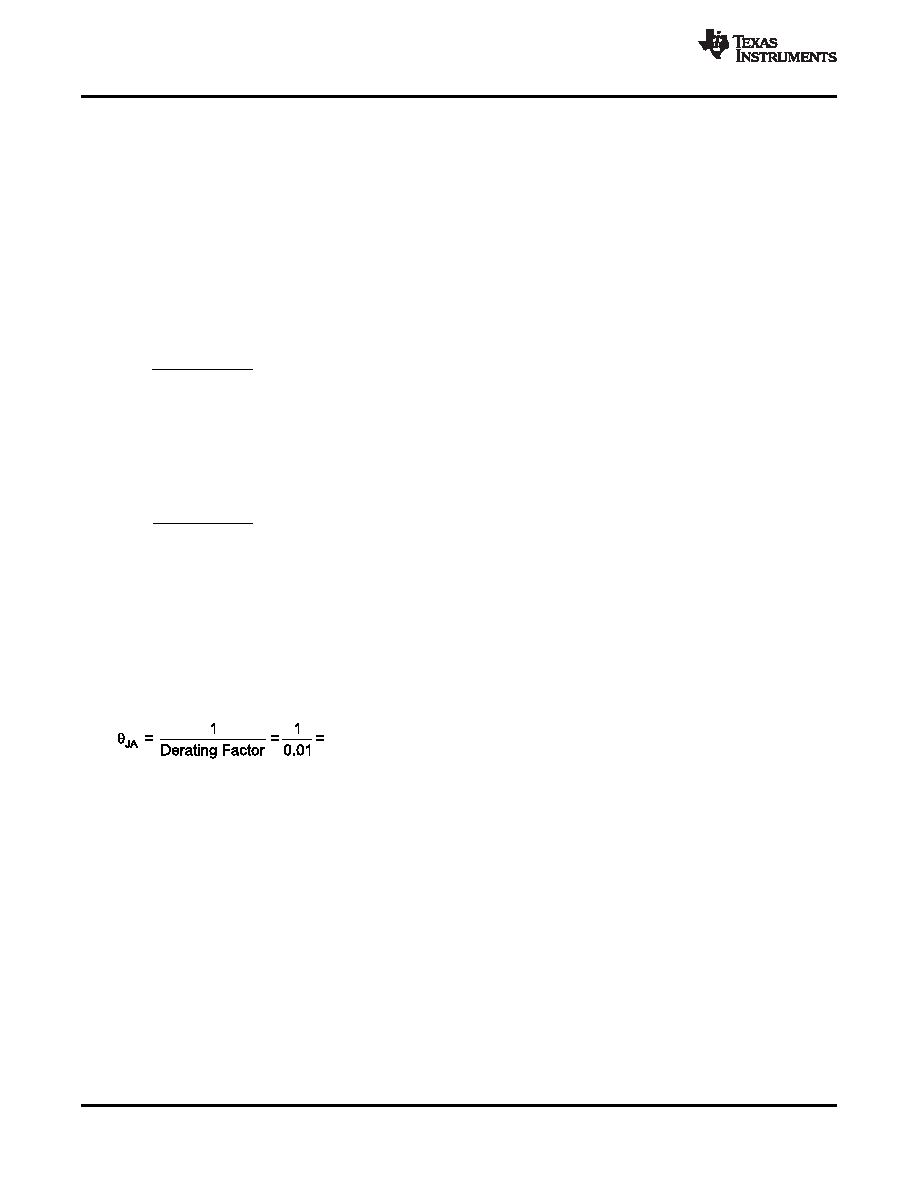
The maximum ambient temperature depends on the heat-sinking ability of the PCB system. The derating factor
for the packages are shown in the dissipation rating table. Converting this to
θ
JA for the WCSP package:
Given
θ
JA of 100°C/W, the maximum allowable junction temperature of 150°C, and the maximum internal
dissipation of 0.4 W (0.2 W per channel) for 1.5 W per channel, 8-
load, 5-V supply, from Figure 9, the
maximum ambient temperature can be calculated with the following equation.
Equation 4 shows that the calculated maximum ambient temperature is 110°C at maximum power dissipation
with a 5-V supply and 8-
a load. The TPA2017D2 is designed with thermal protection that turns the device off
when the junction temperature surpasses 150°C to prevent damage to the IC. Also, using speakers more
resistive than 8-
dramatically increases the thermal performance by reducing the output current and increasing
the efficiency of the amplifier.
In using Class-D amplifiers with CODECs and DACs, sometimes there is an increase in the output noise floor
from the audio amplifier. This occurs when mixing of the output frequencies of the CODEC/DAC mix with the
switching frequencies of the audio amplifier input stage. The noise increase can be solved by placing a low-pass
filter between the CODEC/DAC and audio amplifier. This filters off the high frequencies that cause the problem
and allow proper performance. See the functional block diagram.
12
Copyright 2009, Texas Instruments Incorporated
Product Folder Link(s): TPA2017D2
相关PDF资料 |
PDF描述 |
|---|---|
| TPA2026D2YZHR | AUDIO AMPLIFIER, PBGA16 |
| TPA2026D2YZHT | AUDIO AMPLIFIER, PBGA16 |
| TPA2028D1YZFR | 3 W, 1 CHANNEL, AUDIO AMPLIFIER, PBGA9 |
| TPA2028D1YZFT | 3 W, 1 CHANNEL, AUDIO AMPLIFIER, PBGA9 |
| TPA2031D1YZFT | 2.5 W, 2 CHANNEL, AUDIO AMPLIFIER, BGA9 |
相关代理商/技术参数 |
参数描述 |
|---|---|
| TPA2017D2RTJT | 制造商:Texas Instruments 功能描述:; No. of Channels:2; Output Power Po rm |
| TPA2017D2V2RTJR | 制造商:Texas Instruments 功能描述: |
| TPA2018D1 | 制造商:TI 制造商全称:Texas Instruments 功能描述:3-W Mono Class-D Audio Amplifier with SmartGain AGC/DRC |
| TPA2018D1YZFEVM | 功能描述:音频 IC 开发工具 TPA2018D1YZF Eval Mod RoHS:否 制造商:Texas Instruments 产品:Evaluation Kits 类型:Audio Amplifiers 工具用于评估:TAS5614L 工作电源电压:12 V to 38 V |
| TPA2018D1YZFR | 功能描述:音频放大器 3W Mono Class-D Aud Amp RoHS:否 制造商:STMicroelectronics 产品:General Purpose Audio Amplifiers 输出类型:Digital 输出功率: THD + 噪声: 工作电源电压:3.3 V 电源电流: 最大功率耗散: 最大工作温度: 安装风格:SMD/SMT 封装 / 箱体:TQFP-64 封装:Reel |
发布紧急采购,3分钟左右您将得到回复。