- 您现在的位置:买卖IC网 > PDF目录69499 > TPS2051D (TEXAS INSTRUMENTS INC) SPECIALTY ANALOG CIRCUIT, PDSO8 PDF资料下载
参数资料
| 型号: | TPS2051D |
| 厂商: | TEXAS INSTRUMENTS INC |
| 元件分类: | 模拟信号调理 |
| 英文描述: | SPECIALTY ANALOG CIRCUIT, PDSO8 |
| 封装: | GREEN, PLASTIC, SOIC-8 |
| 文件页数: | 1/25页 |
| 文件大小: | 566K |
| 代理商: | TPS2051D |
TPS2041, TPS2051
POWER-DISTRIBUTION SWITCHES
SLVS172A –AUGUST 1998 – REVISED APRIL 1999
1
POST OFFICE BOX 655303
DALLAS, TEXAS 75265
D 135-m -Maximum (5-V Input) High-Side
MOSFET Switch
D 500 mA Continuous Current
D Short-Circuit and Thermal Protection With
Overcurrent Logic Output
D Operating Range . . . 2.7 V to 5.5 V
D Logic-Level Enable Input
D 2.5-ms Typical Rise Time
D Undervoltage Lockout
D 10 A Maximum Standby Supply Current
D Bidirectional Switch
D Available in 8-pin SOIC and PDIP Packages
D Ambient Temperature Range, –40°C to 85°C
D 2-kV Human-Body-Model, 200-V
Machine-Model ESD Protection
D UL Listed – File No. E169910
description
The TPS2041 and TPS2051 power distribution switches are intended for applications where heavy capacitive
loads and short circuits are likely to be encountered. The TPS2041 and the TPS2051 are 135-m
N-channel
MOSFET high-side power switches. Each switch is controlled by a logic enable compatible with 5-V and 3-V
logic. Gate drive is provided by an internal charge pump that controls the power-switch rise times and fall times
to minimize current surges during switching. The charge pump requires no external components and allows
operation from supplies as low as 2.7 V.
When the output load exceeds the current-limit threshold or a short is present, the TPS2041 and TPS2051 limit
the output current to a safe level by switching into a constant-current mode, pulling the overcurrent (OC) logic
output low. When continuous heavy overloads and short circuits increase the power dissipation in the switch,
causing the junction temperature to rise, a thermal protection circuit shuts off the switch in overcurrent to prevent
damage. Recovery from a thermal shutdown is automatic once the device has cooled sufficiently. Internal
circuitry ensures the switch remains off until valid input voltage is present.
The TPS2041 and TPS2051 are designed to limit at 0.9-A load. These power distribution switches are available
in 8-pin small-outline integrated circuit (SOIC) and 8-pin plastic dual-in-line packages (PDIP) and operate over
an ambient temperature range of –40
°C to 85°C.
AVAILABLE OPTIONS
RECOMMENDED
MAXIMUM CONTINUOUS
TYPICAL SHORT-CIRCUIT
PACKAGED DEVICES
TA
ENABLE
MAXIMUM CONTINUOUS
LOAD CURRENT
(A)
CURRENT LIMIT AT 25
°C
(A)
SOIC
(D)
PDIP
(P)
–40
°C to 85°C
Active low
0.5
0.9
TPS2041D
TPS2041P
–40
°C to 85°C
Active high
0.5
0.9
TPS2051D
TPS2051P
The D package is available taped and reeled. Add an R suffix to device type (e.g., TPS2041DR)
Copyright
1999, Texas Instruments Incorporated
This document contains information on products in more than one phase
of development. The status of each device is indicated on the page(s)
specifying its electrical characteristics.
Please be aware that an important notice concerning availability, standard warranty, and use in critical applications of
Texas Instruments semiconductor products and disclaimers thereto appears at the end of this data sheet.
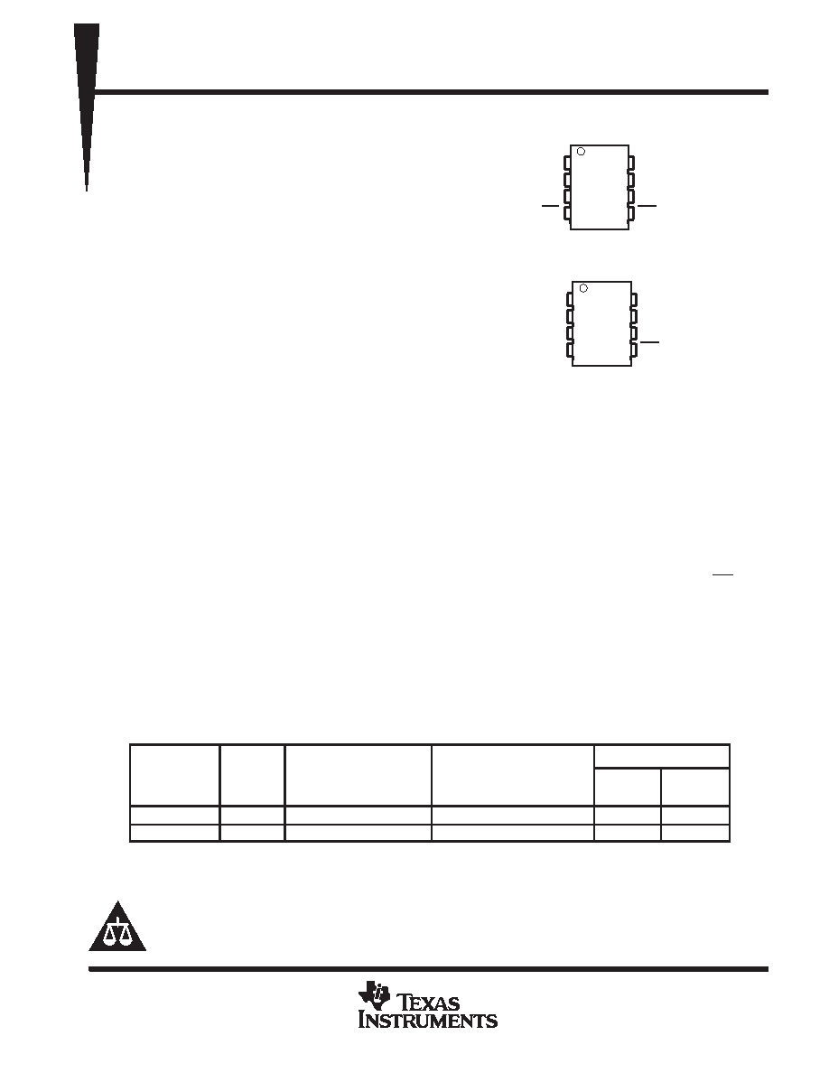
1
2
3
4
8
7
6
5
GND
IN
EN
OUT
OC
TPS2041
D OR P PACKAGE
(TOP VIEW)
1
2
3
4
8
7
6
5
GND
IN
EN
OUT
OC
TPS2051
D OR P PACKAGE
(TOP VIEW)
相关PDF资料 |
PDF描述 |
|---|---|
| TPS2051P | SPECIALTY ANALOG CIRCUIT, PDIP8 |
| TPS2041P | SPECIALTY ANALOG CIRCUIT, PDIP8 |
| TPS2060DRBR | 2-CHANNEL POWER SUPPLY SUPPORT CKT, PDSO8 |
| TPS2064DRBT | 2-CHANNEL POWER SUPPLY SUPPORT CKT, PDSO8 |
| TPS2064DRBR | 2-CHANNEL POWER SUPPLY SUPPORT CKT, PDSO8 |
相关代理商/技术参数 |
参数描述 |
|---|---|
| TPS2051DG4 | 功能描述:电源开关 IC - USB 0.7A 2.7-5.5V Hi RoHS:否 制造商:Micrel 电源电压-最小:2.7 V 电源电压-最大:5.5 V 最大工作温度:+ 85 C 最小工作温度:- 40 C 封装 / 箱体:SOIC-8 封装:Tube |
| TPS2051DR | 功能描述:电源开关 IC - USB DUAL HI-SIDE MOSFET RoHS:否 制造商:Micrel 电源电压-最小:2.7 V 电源电压-最大:5.5 V 最大工作温度:+ 85 C 最小工作温度:- 40 C 封装 / 箱体:SOIC-8 封装:Tube |
| TPS2051DRG4 | 功能描述:电源开关 IC - USB DUAL HI-SIDE MOSFET RoHS:否 制造商:Micrel 电源电压-最小:2.7 V 电源电压-最大:5.5 V 最大工作温度:+ 85 C 最小工作温度:- 40 C 封装 / 箱体:SOIC-8 封装:Tube |
| TPS2051P | 功能描述:电源开关 IC - USB 0.7A 2.7-5.5V Hi RoHS:否 制造商:Micrel 电源电压-最小:2.7 V 电源电压-最大:5.5 V 最大工作温度:+ 85 C 最小工作温度:- 40 C 封装 / 箱体:SOIC-8 封装:Tube |
| TPS2051PE4 | 功能描述:电源开关 IC - USB DUAL HI-SIDE MOSFET RoHS:否 制造商:Micrel 电源电压-最小:2.7 V 电源电压-最大:5.5 V 最大工作温度:+ 85 C 最小工作温度:- 40 C 封装 / 箱体:SOIC-8 封装:Tube |
发布紧急采购,3分钟左右您将得到回复。