- 您现在的位置:买卖IC网 > PDF目录68418 > TPS2100D (TEXAS INSTRUMENTS INC) 2-CHANNEL POWER SUPPLY SUPPORT CKT, PDSO8 PDF资料下载
参数资料
| 型号: | TPS2100D |
| 厂商: | TEXAS INSTRUMENTS INC |
| 元件分类: | 电源管理 |
| 英文描述: | 2-CHANNEL POWER SUPPLY SUPPORT CKT, PDSO8 |
| 封装: | PLASTIC, SOIC-8 |
| 文件页数: | 15/20页 |
| 文件大小: | 490K |
| 代理商: | TPS2100D |
TPS2100, TPS2101
VAUX POWER-DISTRIBUTION SWITCHES
SLVS197D – JUNE 1999 – REVISED JUNE 2000
4
POST OFFICE BOX 655303
DALLAS, TEXAS 75265
detailed description (continued)
enable
The logic enable will turn on the IN2-OUT power switch when a logic high is present on EN (TPS2100) or logic
low is present on EN (TPS2101). A logic low input on EN (TPS2100) or logic high on EN (TPS2101) restores
bias to the drive and control circuits and turns on the IN1-OUT power switch. The enable input is compatible
with both TTL and CMOS logic levels.
the VAUX application for CardBus controllers
The PC Card specification requires the support of VAUX to the CardBus controller as well as to the PC Card
sockets. Both are 3.3-V requirements; however the CardBus controller’s current demand from the VAUX supply
is limited to 10
A, whereas the PC Card may consume as much as 200 mA. In either implementation, if support
of a wake-up event is required, the controller and the socket will transition from the 3.3-V VCC rail to the 3.3-V
VAUX rail when the equipment moves into a low power mode such as D3. The transition from VCC to VAUX needs
to be seamless in order to maintain all memory and register information in the system. If VAUX is not supported,
the system will lose all register information when it transitions to the D3 state.
absolute maximum ratings over operating free-air temperature (unless otherwise noted)
Input voltage range, VI(IN1) (see Note1)
– 0.3 V to 5 V
. . . . . . . . . . . . . . . . . . . . . . . . . . . . . . . . . . . . . . . . . . . . . . .
Input voltage range, VI(IN2) (see Note1)
– 0.3 V to 5 V
. . . . . . . . . . . . . . . . . . . . . . . . . . . . . . . . . . . . . . . . . . . . . . .
Input voltage range, VI at EN or EN
– 0.3 V to 5 V
. . . . . . . . . . . . . . . . . . . . . . . . . . . . . . . . . . . . . . . . . . . . . . . . . .
Output voltage range, VO (see Note 1)
– 0.3 V to 5 V
. . . . . . . . . . . . . . . . . . . . . . . . . . . . . . . . . . . . . . . . . . . . . . .
Continuous output current, IO(IN1)
700 mA
. . . . . . . . . . . . . . . . . . . . . . . . . . . . . . . . . . . . . . . . . . . . . . . . . . . . . . . .
Continuous output current, IO(IN2)
70 mA
. . . . . . . . . . . . . . . . . . . . . . . . . . . . . . . . . . . . . . . . . . . . . . . . . . . . . . . . .
Continuous total power dissipation
See dissipation rating table
. . . . . . . . . . . . . . . . . . . . . . . . . . . . . . . . . . . . . . .
Operating virtual junction temperature range, TJ
–40
°C to 85°C
. . . . . . . . . . . . . . . . . . . . . . . . . . . . . . . . . . . . . .
Storage temperature range, Tstg
–65
°C to 150°C
. . . . . . . . . . . . . . . . . . . . . . . . . . . . . . . . . . . . . . . . . . . . . . . . . . .
Lead temperature soldering 1,6 mm (1/16 inch) from case for 10 seconds
260
°C
. . . . . . . . . . . . . . . . . . . . . . .
Electrostatic discharge (ESD) protection: Human body model
2 kV
. . . . . . . . . . . . . . . . . . . . . . . . . . . . . . . . . . .
Machine model
200 V
. . . . . . . . . . . . . . . . . . . . . . . . . . . . . . . . . . . . . .
Charged device model (CDM)
750 V
. . . . . . . . . . . . . . . . . . . . . . . . .
Stresses beyond those listed under “absolute maximum ratings” may cause permanent damage to the device. These are stress ratings only, and
functional operation of the device at these or any other conditions beyond those indicated under “recommended operating conditions” is not
implied. Exposure to absolute-maximum-rated conditions for extended periods may affect device reliability.
NOTE 1: All voltages are with respect to GND.
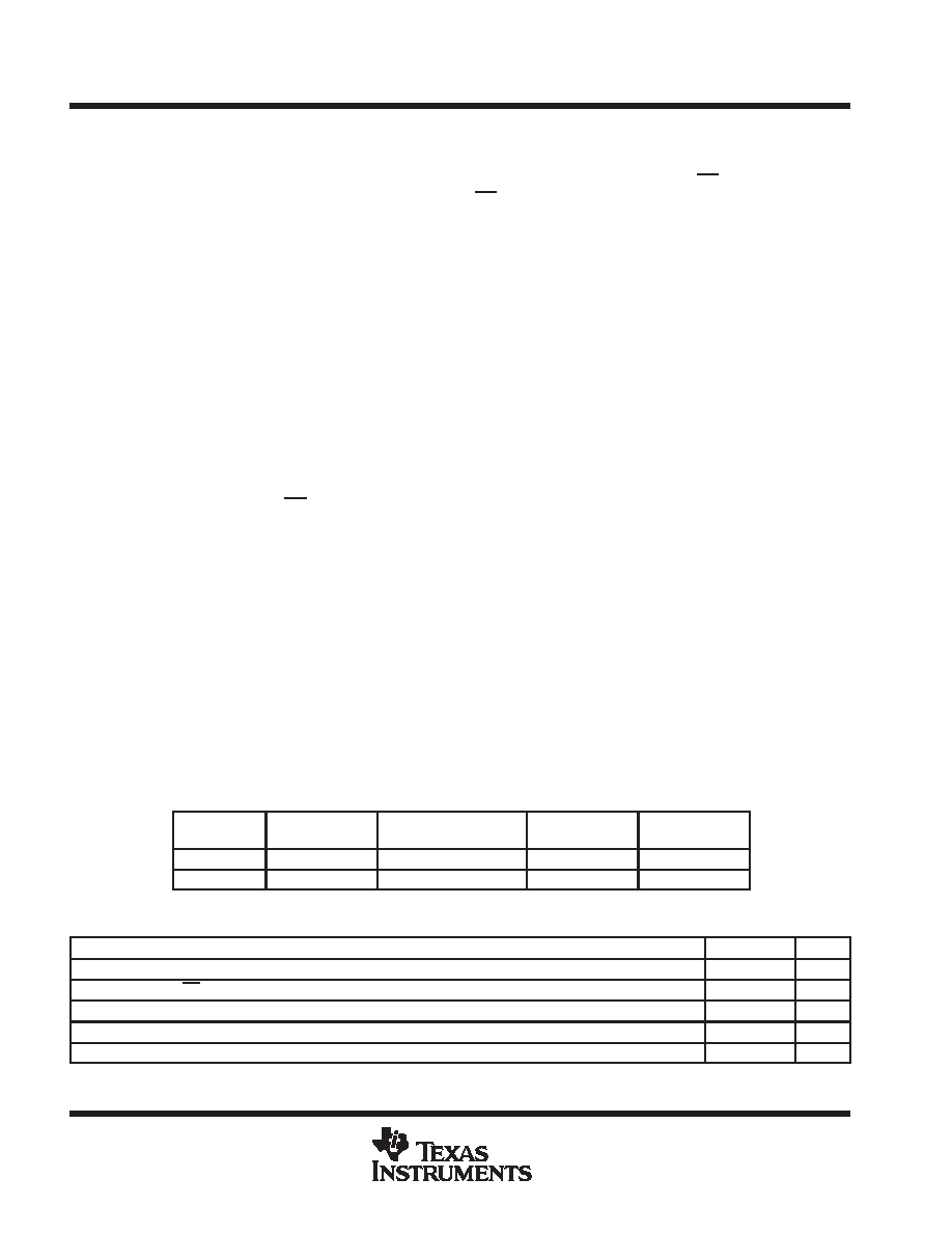
DISSIPATION RATING TABLE
PACKAGE
TA < 25°C
POWER RATING
DERATING FACTOR
ABOVE TA = 25°C
TA = 70°C
POWER RATING
TA = 85°C
POWER RATING
DBV
309 mW
3.1 mW/
°C
170 mW
123 mW
D
568 mW
5.7 mW/
°C
313 mW
227 mW
recommended operating conditions
MIN
MAX
UNIT
Input voltage, VI(INx)
2.7
4
V
Input voltage, VI at EN and EN
0
4
V
Continuous output current, IO(IN1)
500
mA
Continuous output current, IO(IN2)
10
mA
Operating virtual junction temperature, TJ
–40
85
°C
The device can deliver up to 220 mA at IO(IN2). However, operation at the higher current levels will result in greater voltage drop across the device,
and greater voltage droop when switching between IN1 and IN2.
相关PDF资料 |
PDF描述 |
|---|---|
| TPS2101DBVRG4 | 2-CHANNEL POWER SUPPLY SUPPORT CKT, PDSO5 |
| TPS3103E12DBVT | 1-CHANNEL POWER SUPPLY SUPPORT CKT, PDSO6 |
| TPS3110E15DBVR | 1-CHANNEL POWER SUPPLY MANAGEMENT CKT, PDSO6 |
| TPS3106E09DBVTG4 | 1-CHANNEL POWER SUPPLY SUPPORT CKT, PDSO6 |
| TPS3110E12DBVR | 1-CHANNEL POWER SUPPLY MANAGEMENT CKT, PDSO6 |
相关代理商/技术参数 |
参数描述 |
|---|---|
| TPS2100DBVR | 功能描述:电源开关 IC - 配电 Dual In/Single Out MOSFET RoHS:否 制造商:Exar 输出端数量:1 开启电阻(最大值):85 mOhms 开启时间(最大值):400 us 关闭时间(最大值):20 us 工作电源电压:3.2 V to 6.5 V 电源电流(最大值): 最大工作温度:+ 85 C 安装风格:SMD/SMT 封装 / 箱体:SOT-23-5 |
| TPS2100DBVRG4 | 功能描述:电源开关 IC - 配电 Dual In/Single Out MOSFET RoHS:否 制造商:Exar 输出端数量:1 开启电阻(最大值):85 mOhms 开启时间(最大值):400 us 关闭时间(最大值):20 us 工作电源电压:3.2 V to 6.5 V 电源电流(最大值): 最大工作温度:+ 85 C 安装风格:SMD/SMT 封装 / 箱体:SOT-23-5 |
| TPS2100DBVT | 功能描述:电源开关 IC - 配电 Dual In/Single Out MOSFET RoHS:否 制造商:Exar 输出端数量:1 开启电阻(最大值):85 mOhms 开启时间(最大值):400 us 关闭时间(最大值):20 us 工作电源电压:3.2 V to 6.5 V 电源电流(最大值): 最大工作温度:+ 85 C 安装风格:SMD/SMT 封装 / 箱体:SOT-23-5 |
| TPS2100DBVTG4 | 功能描述:电源开关 IC - 配电 Dual In/Single Out MOSFET RoHS:否 制造商:Exar 输出端数量:1 开启电阻(最大值):85 mOhms 开启时间(最大值):400 us 关闭时间(最大值):20 us 工作电源电压:3.2 V to 6.5 V 电源电流(最大值): 最大工作温度:+ 85 C 安装风格:SMD/SMT 封装 / 箱体:SOT-23-5 |
| TPS2101D | 功能描述:电源开关 IC - 配电 Dual In/Single Out MOSFET RoHS:否 制造商:Exar 输出端数量:1 开启电阻(最大值):85 mOhms 开启时间(最大值):400 us 关闭时间(最大值):20 us 工作电源电压:3.2 V to 6.5 V 电源电流(最大值): 最大工作温度:+ 85 C 安装风格:SMD/SMT 封装 / 箱体:SOT-23-5 |
发布紧急采购,3分钟左右您将得到回复。