- 您现在的位置:买卖IC网 > PDF目录69503 > TPS2375DG4 (TEXAS INSTRUMENTS INC) 1-CHANNEL POWER SUPPLY SUPPORT CKT, PDSO8 PDF资料下载
参数资料
| 型号: | TPS2375DG4 |
| 厂商: | TEXAS INSTRUMENTS INC |
| 元件分类: | 电源管理 |
| 英文描述: | 1-CHANNEL POWER SUPPLY SUPPORT CKT, PDSO8 |
| 封装: | GREEN, PLASTIC, MS-012AA, SOIC-8 |
| 文件页数: | 5/24页 |
| 文件大小: | 579K |
| 代理商: | TPS2375DG4 |
MAINTAIN POWER SIGNATURE
POWER GOOD
THERMAL PROTECTION
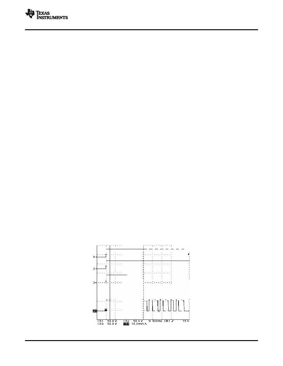
Ch1: VDD @ 50 V/div
CH2: RTN @ 50 V/div
Iin @ 100 mA/div
V(PI) = 44 V, R(ILIM) = 178 kW
CH3: V(PG) @ 50 V/div
data sheet
www.ti.com............................................................................................................................................................ SLVS525B – APRIL 2004 – REVISED APRIL 2008
Once a valid PD has been detected and powered, the PSE uses the maintain power signature (MPS) to
determine when to remove power from the PI. The PSE removes power from that output port if it detects loss of
MPS for 300 ms or more. A valid MPS requires the PD to draw at least 10 mA and also have an ac impedance
less than 26.25 k
in parallel with 0.05 F. TI's reference designs meet the requirements necessary to maintain
power.
The TPS2375 includes a power-good circuit that can be used to signal the PD circuitry that the load capacitor is
fully charged. This pin is intended for use as an enable signal for downstream circuitry. If the converter tries to
start up while inrush is active, and draws a current equal to the inrush limit, a latchup condition occurs in which
the PD never successfully starts. Using the PG pin is the safest way to assure that there are no undesired
interactions between the inrush limit, the converter startup characteristic, and the size of the bulk capacitor.
The PG pin goes to an open-drain state approximately 150 s after the inrush current falls 10% below the
regulated value. PG pulldown current is only assured when the voltage difference between VDD and RTN
exceeds 4 V. This is not a limiting factor because the dc/dc converter should not be able to run from 4 V. The PG
output is pulled to RTN whenever the MOSFET is disabled or is in inrush current limiting.
Referencing PG to RTN simplifies the interface to the downstream dc/dc converter or other circuit because it is
referenced to RTN, not VSS. Care must be used in interfacing the PG pin to the downstream circuits. The pullup
to VDD shown in Figure 1 may not be appropriate for a particular dc/dc converter interface. The PG pin connects
to an internal open-drain, 100-V transistor capable of sinking 2 mA to a voltage below 0.4 V. The PG pin can be
left open if it is not used.
The controller may overheat after operation in current-limit state or classification for an extended period of time,
or if the ambient temperature becomes excessive. The TPS2375 protects itself by disabling the RTN and CLASS
pins when the internal die temperature reaches about 140
°C. It automatically restarts when the die temperature
has fallen approximately 20
°C. If this cycle occurs eight times, then the device latches off until the supply voltage
drops below the lower classification threshold. This feature prevents the part from operating indefinitely in fault,
and ensures that the PSE recognizes the fault condition when using dc MPS. Thermal protection is active
whenever the TPS2375 is not in detection.
Figure 20 shows how the TPS2375 responds when it is enabled into a short. The TPS2375 starts in the inrush
current-limit state when the input voltage exceeds the upper UVLO limit. A power dissipation of over 5 W heats
the die from 25
°C to 140°C in approximately 400 ms. The TPS2375 then shuts down until the die temperature
drops to about 120
°C, which occurs in about 20 ms. This process repeats eight times before the TPS2375
latches off. The PG pin is high because RTN is tied to VDD.
Figure 20. TPS2375 Started Into Short
Copyright 2004–2008, Texas Instruments Incorporated
13
相关PDF资料 |
PDF描述 |
|---|---|
| TPS2377DRG4 | 1-CHANNEL POWER SUPPLY SUPPORT CKT, PDSO8 |
| TPS2377DG4 | 1-CHANNEL POWER SUPPLY SUPPORT CKT, PDSO8 |
| TPS2376PWG4 | 1-CHANNEL POWER SUPPLY SUPPORT CKT, PDSO8 |
| TPS2375PW | 1-CHANNEL POWER SUPPLY SUPPORT CKT, PDSO8 |
| TPS2376DR | 1-CHANNEL POWER SUPPLY SUPPORT CKT, PDSO8 |
相关代理商/技术参数 |
参数描述 |
|---|---|
| TPS2375DR | 功能描述:热插拔功率分布 IEEE 802.3af PoE Pwr Device Cntrler RoHS:否 制造商:Texas Instruments 产品:Controllers & Switches 电流限制: 电源电压-最大:7 V 电源电压-最小:- 0.3 V 工作温度范围: 功率耗散: 安装风格:SMD/SMT 封装 / 箱体:MSOP-8 封装:Tube |
| TPS2375DRG4 | 功能描述:热插拔功率分布 IEEE 802.3af PoE Pwr Device Cntrler RoHS:否 制造商:Texas Instruments 产品:Controllers & Switches 电流限制: 电源电压-最大:7 V 电源电压-最小:- 0.3 V 工作温度范围: 功率耗散: 安装风格:SMD/SMT 封装 / 箱体:MSOP-8 封装:Tube |
| TPS2375EVM | 功能描述:电源管理IC开发工具 TPS2375 POE Powed Device Eval Mod RoHS:否 制造商:Maxim Integrated 产品:Evaluation Kits 类型:Battery Management 工具用于评估:MAX17710GB 输入电压: 输出电压:1.8 V |
| TPS2375PW | 功能描述:热插拔功率分布 IEEE 802.3af PoE Pwr Device Cntrler RoHS:否 制造商:Texas Instruments 产品:Controllers & Switches 电流限制: 电源电压-最大:7 V 电源电压-最小:- 0.3 V 工作温度范围: 功率耗散: 安装风格:SMD/SMT 封装 / 箱体:MSOP-8 封装:Tube |
| TPS2375PW-1 | 功能描述:热插拔功率分布 IEEE 802.3af PoE Pwr Device Cntrler RoHS:否 制造商:Texas Instruments 产品:Controllers & Switches 电流限制: 电源电压-最大:7 V 电源电压-最小:- 0.3 V 工作温度范围: 功率耗散: 安装风格:SMD/SMT 封装 / 箱体:MSOP-8 封装:Tube |
发布紧急采购,3分钟左右您将得到回复。