- 您现在的位置:买卖IC网 > PDF目录69504 > TPS2412PWR (TEXAS INSTRUMENTS INC) SPECIALTY ANALOG CIRCUIT, PDSO8 PDF资料下载
参数资料
| 型号: | TPS2412PWR |
| 厂商: | TEXAS INSTRUMENTS INC |
| 元件分类: | 模拟信号调理 |
| 英文描述: | SPECIALTY ANALOG CIRCUIT, PDSO8 |
| 封装: | GREEN, PLASTIC, TSSOP-8 |
| 文件页数: | 3/25页 |
| 文件大小: | 1052K |
| 代理商: | TPS2412PWR |
TPS2412 vs TPS2413 – MOSFET CONTROL METHODS
N+1 POWER SUPPLY – TYPICAL CONNECTION
C
om
m
on
B
us
Concept
V
D
A
C
G
N
D
G
A
T
E
P
o
w
er
C
o
n
v
er
si
o
n
B
lo
ck
Input
Voltage
Power
Bus
Implementation
C
(B
YP)
B
Y
P
DC/DC
Converter
DC/DC
Converter
www.ti.com.......................................................................................................................................... SLVS728B – JANUARY 2007 – REVISED SEPTEMBER 2008
The TPS2412 control method yields several benefits. First, the low-current GATE driver provides a gentle turn-on
and turn-off for slowly rising and falling input voltage. Second, it reduces the tendency for on/off cycling of a
comparator based solution at light loads. Third, it avoids reverse currents if the fast turn-off threshold is left
positive. The drawback to this method is that the MOSFET appears to have a high resistance at light load when
the regulation is active. A momentary output voltage droop occurs when a large step load is applied from a
light-load condition. The TPS2412 is a better solution for a mid-rail bus that is re-regulated.
The TPS2413 turns the MOSFET on if V(AC) is greater than 10 mV, and the rapid turn-off is activated at the
programmed negative threshold. There is no linear control range and slow turn-off. The disadvantage is that the
turn-off threshold must be negative (unless a minimum load is always present) permitting a continuous reverse
current. Under a dynamic reverse voltage fault, the lower threshold voltage may permit a higher peak reverse
current. There are a number of advantages to this control method. Step loads from a light load condition are
handled without a voltage droop beyond I × R. If the redundant converter fails, applications with redundant
synchronous converters may permit a small amount of reverse current at light load in order to assure that the
MOSFET is all ready on. The TPS2413 is a better solution for low-voltage buses that are not re-regulated, and
that may see large load steps transients.
These applications recommendations are meant as a starting point, with the needs of specific implementations
over-riding them.
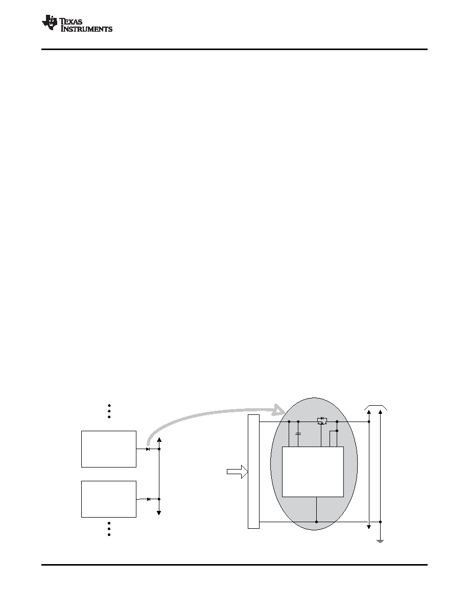
The N+1 power supply configuration shown in Figure 12 is used where multiple power supplies are paralleled for
either higher capacity, redundancy or both. If it takes N supplies to power the load, adding an extra, identical unit
in parallel permits the load to continue operation in the event that any one of the N supplies fails. The supplies
are ORed together, rather than directly connected to the bus, to isolate the converter output from the bus when it
is plugged-in or fails short. The TPS2412/13 with an external MOSFET emulates the function of the ORing diode.
It is possible for a malfunctioning converter in an ORed topology to create a bus overvoltage if the loading is less
than the converter's capacity (e.g. N = 1). The ORed topology shown cannot protect the bus from this condition,
even if the ORing MOSFET can be turned off. One common solution is to use two MOSFETs in a back-to-back
configuration to provide bidirectional blocking. The TPS2412/13 does not have a provision for forcing the gate off
when the overvoltage condition occurs, use of the TPS2410/11 is recommended.
ORed supplies are usually designed to share power by various means, although the desired operation could
implement an active and standby concept. Sharing approaches include both passive, or voltage droop, and
active methods. Not all of the output ORing devices may be ON depending on the sharing control method, bus
loading, distribution resistances, and TPS2412/13 settings.
Figure 12. N+1 Power Supply Example
Copyright 2007–2008, Texas Instruments Incorporated
11
Product Folder Link(s): TPS2412 TPS2413
相关PDF资料 |
PDF描述 |
|---|---|
| TPS2412DG4 | SPECIALTY ANALOG CIRCUIT, PDSO8 |
| TPS2413D | SPECIALTY ANALOG CIRCUIT, PDSO8 |
| TPS2413PWR | SPECIALTY ANALOG CIRCUIT, PDSO8 |
| TPS2420RSAR | 1-CHANNEL POWER SUPPLY SUPPORT CKT, PQCC16 |
| TPS2458RHBT | 1-CHANNEL POWER SUPPLY SUPPORT CKT, PQCC32 |
相关代理商/技术参数 |
参数描述 |
|---|---|
| TPS2412PWRG4 | 功能描述:热插拔功率分布 N+1 and OR-ing Pwr Rail Controller RoHS:否 制造商:Texas Instruments 产品:Controllers & Switches 电流限制: 电源电压-最大:7 V 电源电压-最小:- 0.3 V 工作温度范围: 功率耗散: 安装风格:SMD/SMT 封装 / 箱体:MSOP-8 封装:Tube |
| TPS2413D | 功能描述:热插拔功率分布 O-ring controller RoHS:否 制造商:Texas Instruments 产品:Controllers & Switches 电流限制: 电源电压-最大:7 V 电源电压-最小:- 0.3 V 工作温度范围: 功率耗散: 安装风格:SMD/SMT 封装 / 箱体:MSOP-8 封装:Tube |
| TPS2413DG4 | 功能描述:热插拔功率分布 O-ring Cntrlr 8pin RoHS:否 制造商:Texas Instruments 产品:Controllers & Switches 电流限制: 电源电压-最大:7 V 电源电压-最小:- 0.3 V 工作温度范围: 功率耗散: 安装风格:SMD/SMT 封装 / 箱体:MSOP-8 封装:Tube |
| TPS2413DR | 功能描述:热插拔功率分布 O-ring controller RoHS:否 制造商:Texas Instruments 产品:Controllers & Switches 电流限制: 电源电压-最大:7 V 电源电压-最小:- 0.3 V 工作温度范围: 功率耗散: 安装风格:SMD/SMT 封装 / 箱体:MSOP-8 封装:Tube |
| TPS2413DRG4 | 功能描述:热插拔功率分布 O-ring Cntrlr 8pin RoHS:否 制造商:Texas Instruments 产品:Controllers & Switches 电流限制: 电源电压-最大:7 V 电源电压-最小:- 0.3 V 工作温度范围: 功率耗散: 安装风格:SMD/SMT 封装 / 箱体:MSOP-8 封装:Tube |
发布紧急采购,3分钟左右您将得到回复。