- 您现在的位置:买卖IC网 > PDF目录98280 > TPS2561DRC (TEXAS INSTRUMENTS INC) 1-CHANNEL POWER SUPPLY SUPPORT CKT, PDSO10 PDF资料下载
参数资料
| 型号: | TPS2561DRC |
| 厂商: | TEXAS INSTRUMENTS INC |
| 元件分类: | 电源管理 |
| 英文描述: | 1-CHANNEL POWER SUPPLY SUPPORT CKT, PDSO10 |
| 封装: | GREEN, SON-10 |
| 文件页数: | 12/24页 |
| 文件大小: | 942K |
| 代理商: | TPS2561DRC |
SLVS930 – DECEMBER 2009
www.ti.com
This integrated circuit can be damaged by ESD. Texas Instruments recommends that all integrated circuits be handled with
appropriate precautions. Failure to observe proper handling and installation procedures can cause damage.
ESD damage can range from subtle performance degradation to complete device failure. Precision integrated circuits may be more
susceptible to damage because very small parametric changes could cause the device not to meet its published specifications.
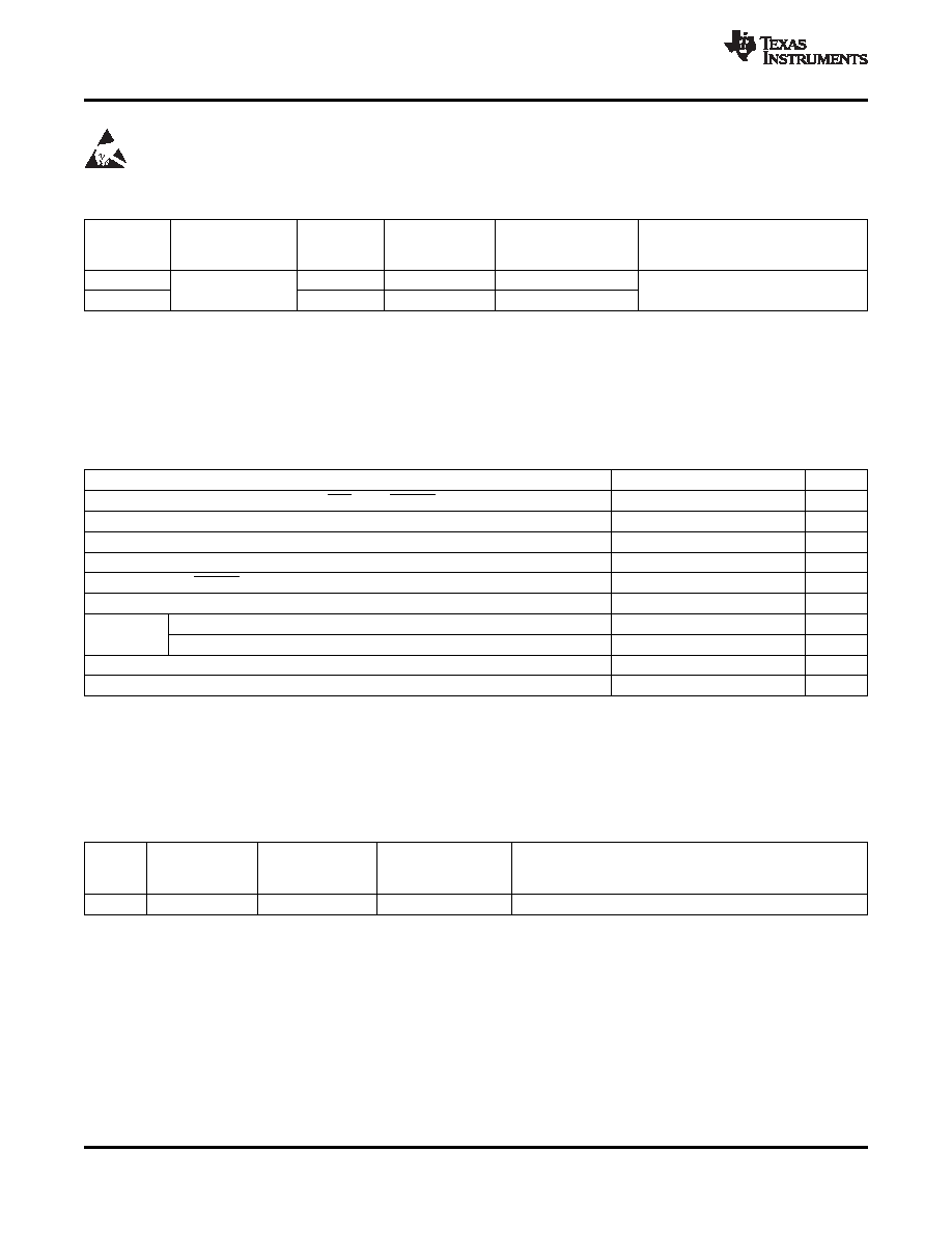
AVAILABLE OPTIONS AND ORDERING INFORMATION
MARKING
RECOMMENDED MAXIMUM
AMBIENT
SON (3)
DEVICE(1)
ENABLE
CONTINUOUS LOAD CURRENT PER
TEMPERATURE (2)
(DRC)
CHANNEL
TPS2560
Active low
TPS2560DRC
2560
–40°C to 85°C
2.5 A
TPS2561
Active high
TPS2561DRC
2561
(1)
For the most current package and ordering information, see the Package Option Addendum at the end of this document, or see the TI
website at www.ti.com.
(2)
Maximum ambient temperature is a function of device junction temperature and system level considerations, such as power dissipation
and board layout. See dissipation rating table and recommended operating conditions for specific information related to these devices.
(3)
Add an R suffix to the device type for tape and reel.
ABSOLUTE MAXIMUM RATINGS
over operating free-air temperature range unless otherwise noted
(1) (2)
VALUE
UNIT
Voltage range on IN, OUTx, ENx or ENx, ILIM, FAULTx
–0.3 to 7
V
Voltage range from IN to OUTx
–7 to 7
V
Continuous output current
Internally Limited
Continuous total power dissipation
See the Dissipation Rating Table
Continuous FAULTx sink current
25
mA
ILIM source current
Internally Limited
mA
HBM
2
kV
ESD
CDM
500
V
ESD – system level (contact/air)(3)
8/15
kV
TJ
Maximum junction temperature
–40 to OTSD2(4)
°C
(1)
Stresses beyond those listed under absolute maximum ratings may cause permanent damage to the device. These are stress ratings
only, and functional operation of the device at these or any other conditions beyond those indicated under recommended operating
conditions is not implied. Exposure to absolute-maximum-rated conditions for extended periods may affect device reliability.
(2)
Voltages are referenced to GND unless otherwise noted.
(3)
Surges per EN61000-4-2, 1999 applied between USB and output ground of the TPS2560EVM (HPA424) evaluation module
(documentation available on the Web.) These were the test level, no the failure threshold.
(4)
Ambient over temperature shutdown threshold
DISSIPATION RATING TABLE
THERMAL
TA ≤ 25°C
RESISTANCE(1)
RESISTANCE
BOARD
PACKAGE
POWER
θJA
θJC
RATING
High-K(2)
DRC
41.6 °C/W
10.7 °C/W
2403 mW
(1)
Mounting per the PowerPADTM Thermally Enhanced Package application report (SLMA002)
(2)
The JEDEC high-K (2s2p) board used to derive this data was a 3in × 3in, multilayer board with 1-ounce internal power and ground
planes and 2-ounce copper traces on top and bottom of the board.
2
Copyright 2009, Texas Instruments Incorporated
相关PDF资料 |
PDF描述 |
|---|---|
| TPS2561DRCT | 1-CHANNEL POWER SUPPLY SUPPORT CKT, PDSO10 |
| TPS3305-20QDRQ1 | 2-CHANNEL POWER SUPPLY MANAGEMENT CKT, PDSO8 |
| TPS3305-18QDRQ1 | 2-CHANNEL POWER SUPPLY MANAGEMENT CKT, PDSO8 |
| TPS3306-20DRG4 | 2-CHANNEL POWER SUPPLY MANAGEMENT CKT, PDSO8 |
| TPS3306-20DGKRG4 | 2-CHANNEL POWER SUPPLY MANAGEMENT CKT, PDSO8 |
相关代理商/技术参数 |
参数描述 |
|---|---|
| TPS2561DRCEVM-424 | 功能描述:交换机 IC 开发工具 Eval Mod for TPS2561 RoHS:否 制造商:Maxim Integrated 产品:Evaluation Kits 类型:USB Power Switches 工具用于评估:MAX4984E 工作电源电压:2.8 V to 5.5 V |
| TPS2561DRCR | 功能描述:电源开关 IC - USB Dual Ch Prec Adj Current-Ltd Pwr Sw RoHS:否 制造商:Micrel 电源电压-最小:2.7 V 电源电压-最大:5.5 V 最大工作温度:+ 85 C 最小工作温度:- 40 C 封装 / 箱体:SOIC-8 封装:Tube |
| TPS2561DRCT | 功能描述:电源开关 IC - USB Dual Ch Prec Adj Current-Ltd Pwr Sw RoHS:否 制造商:Micrel 电源电压-最小:2.7 V 电源电压-最大:5.5 V 最大工作温度:+ 85 C 最小工作温度:- 40 C 封装 / 箱体:SOIC-8 封装:Tube |
| TPS2561QDRCRQ1 | 功能描述:电源开关 IC - USB AC Dual Channel Prec Adj Crnt-Ltd Pwr Sw RoHS:否 制造商:Micrel 电源电压-最小:2.7 V 电源电压-最大:5.5 V 最大工作温度:+ 85 C 最小工作温度:- 40 C 封装 / 箱体:SOIC-8 封装:Tube |
| TPS25740AEVM-741 | 功能描述:LM5175, TPS25740A - Interface, USB Type-C? Evaluation Board 制造商:texas instruments 系列:- 零件状态:新产品 主要用途:接口,USB Type-C? 嵌入式:- 使用的 IC/零件:LM5175, TPS25740A 主要属性:- 辅助属性:- 所含物品:板 标准包装:1 |
发布紧急采购,3分钟左右您将得到回复。