- 您现在的位置:买卖IC网 > PDF目录69515 > TPS61085DGKT (TEXAS INSTRUMENTS INC) 2 A SWITCHING REGULATOR, 1500 kHz SWITCHING FREQ-MAX, PDSO8 PDF资料下载
参数资料
| 型号: | TPS61085DGKT |
| 厂商: | TEXAS INSTRUMENTS INC |
| 元件分类: | 稳压器 |
| 英文描述: | 2 A SWITCHING REGULATOR, 1500 kHz SWITCHING FREQ-MAX, PDSO8 |
| 封装: | GREEN, PLASTIC, MSOP-8 |
| 文件页数: | 3/25页 |
| 文件大小: | 781K |
| 代理商: | TPS61085DGKT |
Setting the Output Voltage
2
18
70
Vref
R
k
A
m
=
W
1
2
1
S
V
R
Vref
=
-
÷
è
(2)
Compensation (COMP)
IN
S
COMP
125 × V
× V × Cout
R
=
L × Iout_max
S
COMP
V × Cout
C
=
5 × Iout_max × R
(3)
Input Capacitor Selection
www.ti.com ...................................................................................................................................................................................................... SLVS859 – JUNE 2008
The output voltage is set by an external resistor divider. Typically, a minimum current of 50
A flowing through
the feedback divider gives good accuracy and noise covering. A standard low side resistor of 18 k
is typically
selected. The resistors are then calculated as:
The regulator loop can be compensated by adjusting the external components connected to the COMP pin. The
COMP pin is the output of the internal transconductance error amplifier. Standard values of RCOMP = 13 k and
CCOMP = 3.3 nF will work for the majority of the applications.
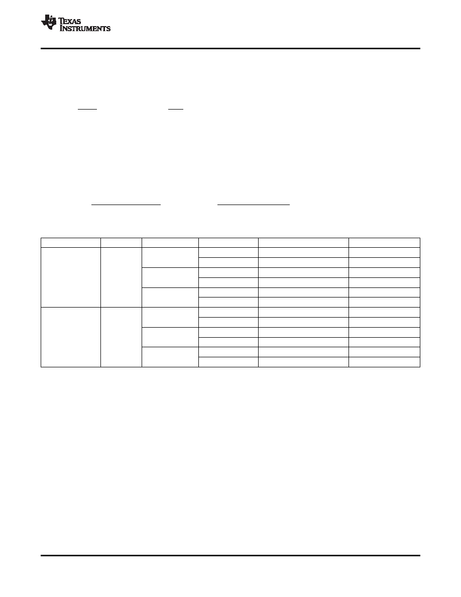
Please refer to Table 3 for dedicated compensation networks giving an improved load transient response. The
following equations can be used to calculate RCOMP and CCOMP:
Table 3. Recommended Compensation Network Values at High/Low Frequency
FREQUENCY
L
VS
VIN ± 20%
RCOMP
CCOMP
5 V
82 k
1.1 nF
15 V
3.3 V
75 k
1.6 nF
5 V
51 k
1.1 nF
High (1.2 MHz)
3.3 H
12 V
3.3 V
47 k
1.6 nF
5 V
30 k
1.1 nF
9 V
3.3 V
27 k
1.6 nF
5 V
43 k
2.2 nF
15 V
3.3 V
39 k
3.3 nF
5 V
27 k
2.2 nF
Low (650 kHz)
6.8 H
12 V
3.3 V
24 k
3.3 nF
5 V
15 k
2.2 nF
9 V
3.3 V
13 k
3.3 nF
Table 3 gives conservatives Rcomp and Comp values for certain inductors, input and output voltages providing a
very stable system. For a faster response time, a higher Rcomp value can be used to enlarge the bandwidth, as
well as a slightly lower value of Ccomp to keep enough phase margin. These adjustments should be performed
in parallel with the load transient response monitoring of TPS61085.
For good input voltage filtering low ESR ceramic capacitors are recommended. TPS61085 has an analog input
IN. Therefore, a 1
F bypass is highly recommended as close as possible to the IC from IN to GND.
One 10
F ceramic input capacitors are sufficient for most of the applications. For better input voltage filtering
this value can be increased. Refer to Table 4 and typical applications for input capacitor recommendations.
Copyright 2008, Texas Instruments Incorporated
11
Product Folder Link(s): TPS61085
相关PDF资料 |
PDF描述 |
|---|---|
| TPS61085PW | 2 A SWITCHING REGULATOR, 1500 kHz SWITCHING FREQ-MAX, PDSO8 |
| TPS61085PWRG4 | 2 A SWITCHING REGULATOR, 1500 kHz SWITCHING FREQ-MAX, PDSO8 |
| TPS61085DGKRG4 | 2 A SWITCHING REGULATOR, 1500 kHz SWITCHING FREQ-MAX, PDSO8 |
| TPS61087DRCR | 4.8 A SWITCHING REGULATOR, 1500 kHz SWITCHING FREQ-MAX, PDSO10 |
| TPS61087DRCT | 4.8 A SWITCHING REGULATOR, 1500 kHz SWITCHING FREQ-MAX, PDSO10 |
相关代理商/技术参数 |
参数描述 |
|---|---|
| TPS61085DGKTG4 | 功能描述:直流/直流开关调节器 650kHz 1.2MHz Step- Up DC-DC Cnvrtr RoHS:否 制造商:International Rectifier 最大输入电压:21 V 开关频率:1.5 MHz 输出电压:0.5 V to 0.86 V 输出电流:4 A 输出端数量: 最大工作温度: 安装风格:SMD/SMT 封装 / 箱体:PQFN 4 x 5 |
| TPS61085EVM-355 | 功能描述:电源管理IC开发工具 TPS61085EVM-355 Eval Mod RoHS:否 制造商:Maxim Integrated 产品:Evaluation Kits 类型:Battery Management 工具用于评估:MAX17710GB 输入电压: 输出电压:1.8 V |
| TPS61085PW | 功能描述:直流/直流开关调节器 650kHz 1.2MHz Step- Up DC-DC Converter RoHS:否 制造商:International Rectifier 最大输入电压:21 V 开关频率:1.5 MHz 输出电压:0.5 V to 0.86 V 输出电流:4 A 输出端数量: 最大工作温度: 安装风格:SMD/SMT 封装 / 箱体:PQFN 4 x 5 |
| TPS61085PWG4 | 功能描述:直流/直流开关调节器 650kHz 1.2MHz Step- Up DC-DC Cnvrtr RoHS:否 制造商:International Rectifier 最大输入电压:21 V 开关频率:1.5 MHz 输出电压:0.5 V to 0.86 V 输出电流:4 A 输出端数量: 最大工作温度: 安装风格:SMD/SMT 封装 / 箱体:PQFN 4 x 5 |
| TPS61085PWR | 功能描述:直流/直流开关调节器 650kHz 1.2MHz Step- Up DC-DC Converter RoHS:否 制造商:International Rectifier 最大输入电压:21 V 开关频率:1.5 MHz 输出电压:0.5 V to 0.86 V 输出电流:4 A 输出端数量: 最大工作温度: 安装风格:SMD/SMT 封装 / 箱体:PQFN 4 x 5 |
发布紧急采购,3分钟左右您将得到回复。