- 您现在的位置:买卖IC网 > PDF目录98284 > TPS62000YEGT (TEXAS INSTRUMENTS INC) 1.6 A SWITCHING REGULATOR, 1000 kHz SWITCHING FREQ-MAX, BGA12 PDF资料下载
参数资料
| 型号: | TPS62000YEGT |
| 厂商: | TEXAS INSTRUMENTS INC |
| 元件分类: | 稳压器 |
| 英文描述: | 1.6 A SWITCHING REGULATOR, 1000 kHz SWITCHING FREQ-MAX, BGA12 |
| 封装: | DSBGA-12 |
| 文件页数: | 7/26页 |
| 文件大小: | 878K |
| 代理商: | TPS62000YEGT |
INPUT CAPACITOR SELECTION
O
RMS
O(max)
I
V
I
= I
1
V
-
÷
è
(7)
The worst case RMS ripple current occurs at D = 0.5 and is calculated as:
O
RMS
I
=
2
LAYOUT CONSIDERATIONS
VIN
1
8
6
7
3
2
9
5
10
4
L1
EN
ILIM
SYNC
GND
FC
PG
PGND
FB
L
TPS62000
+
Co
VO
C3
Ci
VI
R3
R1
C(ff)
R2
+
PG
www.ti.com ........................................................................................................................................... SLVS294E – SEPTEMBER 2000 – REVISED AUGUST 2008
Table 3. Tested Capacitors
CAPACITOR VALUE
ESR/m
COMPONENT SUPPLIER
COMMENTS
10
F
50
Taiyo Yuden JMK316BJ106KL
Ceramic
47
F
100
Sanyo 6TPA47M
POSCAP
68
F
100
Spraque 594D686X0010C2T
Tantalum
Because of the nature of the buck converter having a pulsating input current, a low ESR input capacitor is
required for best input voltage filtering and minimizing the interference with other circuits caused by high input
voltage spikes.
The input capacitor should have a minimum value of 10
F and can be increased without any limit for better input
voltage filtering.
The input capacitor should be rated for the maximum input ripple current calculated as:
Ceramic capacitor show a good performance because of their low ESR value, and they are less sensitive against
voltage transients compared to tantalum capacitors.
Place the input capacitor as close as possible to the input pin of the IC for best performance.
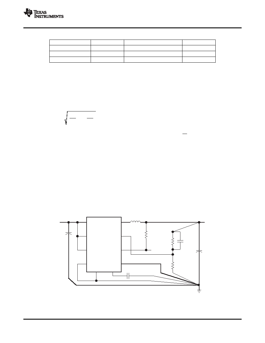
As for all switching power supplies, the layout is an important step in the design especially at high peak currents
and switching frequencies. If the layout is not carefully done, the regulator might show stability problems as well
as EMI problems.
Therefore, use wide and short traces for the main current paths as indicted in bold in Figure 16. The input
capacitor should be placed as close as possible to the IC pins as well as the inductor and output capacitor. Place
the bypass capacitor, C3, as close as possible to the FC pin. The analog ground, GND, and the power ground,
PGND, need to be separated. Use a common ground node as shown in Figure 16 to minimize the effects of
ground noise.
Figure 16. Layout Diagram
Copyright 2000–2008, Texas Instruments Incorporated
15
Product Folder Link(s): TPS62000, TPS62001, TPS62003 TPS62004, TPS62005, TPS62006 TPS62007, TPS62008
相关PDF资料 |
PDF描述 |
|---|---|
| TPS62000YEG | 1.6 A SWITCHING REGULATOR, 1000 kHz SWITCHING FREQ-MAX, BGA12 |
| TPS62000YZG | 1.6 A SWITCHING REGULATOR, 1000 kHz SWITCHING FREQ-MAX, BGA12 |
| TPS62080DSG | 0.002 A SWITCHING REGULATOR, PDSO8 |
| TPS62082DSGR | 0.002 A SWITCHING REGULATOR, PDSO8 |
| TPS62082DSGT | 0.002 A SWITCHING REGULATOR, PDSO8 |
相关代理商/技术参数 |
参数描述 |
|---|---|
| TPS62000YZGR | 功能描述:开关变换器、稳压器与控制器 Adj 600-mA 95% Eff Step-Down Converter RoHS:否 制造商:Texas Instruments 输出电压:1.2 V to 10 V 输出电流:300 mA 输出功率: 输入电压:3 V to 17 V 开关频率:1 MHz 工作温度范围: 安装风格:SMD/SMT 封装 / 箱体:WSON-8 封装:Reel |
| TPS62000YZGT | 功能描述:开关变换器、稳压器与控制器 Adj 600-mA 95% Eff Step-Down Conv RoHS:否 制造商:Texas Instruments 输出电压:1.2 V to 10 V 输出电流:300 mA 输出功率: 输入电压:3 V to 17 V 开关频率:1 MHz 工作温度范围: 安装风格:SMD/SMT 封装 / 箱体:WSON-8 封装:Reel |
| TPS62001DGS | 功能描述:直流/直流开关调节器 0.9V Out 600mA Step-Down Con RoHS:否 制造商:International Rectifier 最大输入电压:21 V 开关频率:1.5 MHz 输出电压:0.5 V to 0.86 V 输出电流:4 A 输出端数量: 最大工作温度: 安装风格:SMD/SMT 封装 / 箱体:PQFN 4 x 5 |
| TPS62001DGSG4 | 功能描述:直流/直流开关调节器 0.9V Out 600mA Step-Down Con RoHS:否 制造商:International Rectifier 最大输入电压:21 V 开关频率:1.5 MHz 输出电压:0.5 V to 0.86 V 输出电流:4 A 输出端数量: 最大工作温度: 安装风格:SMD/SMT 封装 / 箱体:PQFN 4 x 5 |
| TPS62001DGSR | 功能描述:开关变换器、稳压器与控制器 0.9V Out 600mA Step-Down Con RoHS:否 制造商:Texas Instruments 输出电压:1.2 V to 10 V 输出电流:300 mA 输出功率: 输入电压:3 V to 17 V 开关频率:1 MHz 工作温度范围: 安装风格:SMD/SMT 封装 / 箱体:WSON-8 封装:Reel |
发布紧急采购,3分钟左右您将得到回复。