- 您现在的位置:买卖IC网 > PDF目录69517 > TPS62223DDCT (TEXAS INSTRUMENTS INC) 0.4 A SWITCHING REGULATOR, 1850 kHz SWITCHING FREQ-MAX, PDSO5 PDF资料下载
参数资料
| 型号: | TPS62223DDCT |
| 厂商: | TEXAS INSTRUMENTS INC |
| 元件分类: | 稳压器 |
| 英文描述: | 0.4 A SWITCHING REGULATOR, 1850 kHz SWITCHING FREQ-MAX, PDSO5 |
| 封装: | GREEN, PLASTIC, TSOT-23, 5 PIN |
| 文件页数: | 6/24页 |
| 文件大小: | 640K |
| 代理商: | TPS62223DDCT |
C2 +
1
2
p
P
R2
+
1
2
p
8 kHz
R2
VI
GND
EN
SW
FB
C3
4.7
F
L1
4.7
H
C4
10
F
TPS62220
VI
2.5 V 6 V
VO
1.8 V / 400 mA
R1
470k
R2
180k
C1
15 pF
C2
100 pF
INDUCTOR SELECTION
DI =V
x
L
O
I max=I max+
L
O
1-
V
O
DIL
V
I
2
L xf
SLVS491E – SEPTEMBER 2003 – REVISED FEBRUARY 2009....................................................................................................................................... www.ti.com
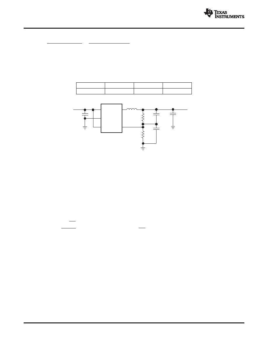
The pole is calculated as:
with R2 = lower resistor of voltage divider and C2 = lower capacitor of voltage divider.
For an output filter combination of L = 4.7
H and C
O = 10 F, C1 and C2 must be selected to place a zero at 22
kHz, and a pole at 8 kHz. Choose components close to the calculated values.
Table 2. Compensation Selection
L
CO
fZ
fP
4.7
H
10
F, 22 F
22 kHz
8 kHz
Figure 15. Typical Application Circuit for the TPS62220 With Adjustable Output Voltage
For high efficiencies, the inductor should have a low dc resistance to minimize conduction losses. Especially at
high-switching frequencies the core material has a higher impact on efficiency. When using small chip inductors,
the efficiency is reduced mainly due to higher inductor core losses. This needs to be considered when selecting
the appropriate inductor. The inductor value determines the inductor ripple current. The larger the inductor value,
the smaller the inductor ripple current and the lower the conduction losses of the converter. Conversely, larger
inductor values cause a slower load transient response. To avoid saturation of the inductor, the inductor should
be rated at least for the maximum output current of the converter plus the inductor ripple current that is
calculated as:
where:
f = switching frequency (1.25-MHz typical, 800-kHz minimal)
L = inductor value
ΔI
L = peak-to-peak inductor ripple current
I
L,max = maximum inductor current
The highest inductor current occurs at maximum Vin. A more conservative approach is to select the inductor
current rating just for the maximum switch current of 880 mA. SeeTable 3 for inductor selection.
14
Copyright 2003–2009, Texas Instruments Incorporated
相关PDF资料 |
PDF描述 |
|---|---|
| TPS62228DDCT | 0.4 A SWITCHING REGULATOR, 1850 kHz SWITCHING FREQ-MAX, PDSO5 |
| TPS62221DDCTG4 | 0.4 A SWITCHING REGULATOR, 1850 kHz SWITCHING FREQ-MAX, PDSO5 |
| TPS62220DDCR | 0.4 A SWITCHING REGULATOR, 1850 kHz SWITCHING FREQ-MAX, PDSO5 |
| TPS62224DDCRG4 | 0.4 A SWITCHING REGULATOR, 1850 kHz SWITCHING FREQ-MAX, PDSO5 |
| TPS62229DDCTG4 | 0.4 A SWITCHING REGULATOR, 1850 kHz SWITCHING FREQ-MAX, PDSO5 |
相关代理商/技术参数 |
参数描述 |
|---|---|
| TPS62223DDCTG4 | 功能描述:直流/直流开关调节器 2.3V Out 400mA Step-Down Converter RoHS:否 制造商:International Rectifier 最大输入电压:21 V 开关频率:1.5 MHz 输出电压:0.5 V to 0.86 V 输出电流:4 A 输出端数量: 最大工作温度: 安装风格:SMD/SMT 封装 / 箱体:PQFN 4 x 5 |
| TPS62224DDCR | 功能描述:直流/直流开关调节器 1.6V Out 400mA Step-Down Converter RoHS:否 制造商:International Rectifier 最大输入电压:21 V 开关频率:1.5 MHz 输出电压:0.5 V to 0.86 V 输出电流:4 A 输出端数量: 最大工作温度: 安装风格:SMD/SMT 封装 / 箱体:PQFN 4 x 5 |
| TPS62224DDCRG4 | 功能描述:直流/直流开关调节器 1.6V Out 400mA Step-Down Converter RoHS:否 制造商:International Rectifier 最大输入电压:21 V 开关频率:1.5 MHz 输出电压:0.5 V to 0.86 V 输出电流:4 A 输出端数量: 最大工作温度: 安装风格:SMD/SMT 封装 / 箱体:PQFN 4 x 5 |
| TPS62224DDCT | 功能描述:直流/直流开关调节器 1.6V Out 400mA Step-Down Converter RoHS:否 制造商:International Rectifier 最大输入电压:21 V 开关频率:1.5 MHz 输出电压:0.5 V to 0.86 V 输出电流:4 A 输出端数量: 最大工作温度: 安装风格:SMD/SMT 封装 / 箱体:PQFN 4 x 5 |
| TPS62224DDCTG4 | 功能描述:直流/直流开关调节器 1.6V Out 400mA 95% Eff St-Down Cnvrtr RoHS:否 制造商:International Rectifier 最大输入电压:21 V 开关频率:1.5 MHz 输出电压:0.5 V to 0.86 V 输出电流:4 A 输出端数量: 最大工作温度: 安装风格:SMD/SMT 封装 / 箱体:PQFN 4 x 5 |
发布紧急采购,3分钟左右您将得到回复。