- 您现在的位置:买卖IC网 > PDF目录272823 > TPS62305DRCR (TEXAS INSTRUMENTS INC) 0.89 A SWITCHING REGULATOR, 3350 kHz SWITCHING FREQ-MAX, PDSO10 PDF资料下载
参数资料
| 型号: | TPS62305DRCR |
| 厂商: | TEXAS INSTRUMENTS INC |
| 元件分类: | 稳压器 |
| 英文描述: | 0.89 A SWITCHING REGULATOR, 3350 kHz SWITCHING FREQ-MAX, PDSO10 |
| 封装: | 3 X 3 MM, GREEN, PLASTIC, SON-10 |
| 文件页数: | 13/37页 |
| 文件大小: | 1401K |
| 代理商: | TPS62305DRCR |
第1页第2页第3页第4页第5页第6页第7页第8页第9页第10页第11页第12页当前第13页第14页第15页第16页第17页第18页第19页第20页第21页第22页第23页第24页第25页第26页第27页第28页第29页第30页第31页第32页第33页第34页第35页第36页第37页
www.ti.com
INPUT CAPACITOR SELECTION
CHECKING LOOP STABILITY
PROGRAMMING THE OUTPUT VOLTAGE WITH A DAC
AVIN
VIN
SW
TPS62300
L
ADJ
PGND
AGND
VOUT
EN
MODE/SYNC
A
FB
A
1
2
3
8
7
10
6
4
5
9
VO =1.5xV(DAC)
V(DAC)
CO
RF
CF
CI
VI
10kW
SLVS528E – JULY 2004 – REVISED NOVEMBER 2007
Because of the nature of the buck converter having a pulsating input current, a low ESR input capacitor is
required to prevent large voltage transients that can cause misbehavior of the device or interferences with other
circuits in the system. For most applications, a 2.2-
F or 4.7-F capacitor is sufficient.
Take care when using only ceramic input capacitors. When a ceramic capacitor is used at the input and the
power is being supplied through long wires, such as from a wall adapter, a load step at the output can induce
ringing at the VIN pin. This ringing can couple to the output and be mistaken as loop instability or could even
damage the part.
The first step of circuit and stability evaluation is to look from a steady-state perspective at the following signals:
Switching node, SW
Inductor current, I
L
Output ripple voltage, V
O(AC)
These are the basic signals that need to be measured when evaluating a switching converter. When the
switching waveform shows large duty cycle jitter or the output voltage or inductor current shows oscillations, the
regulation loop may be unstable. This is often a result of board layout and/or L-C combination.
As a next step in the evaluation of the regulation loop, the load transient response is tested. The time between
the application of the load transient and the turn on of the P-channel MOSFET, the output capacitor must supply
all of the current required by the load. VO immediately shifts by an amount equal to ΔI(LOAD) x ESR, where ESR
is the effective series resistance of CO. ΔI(LOAD) begins to charge or discharge CO generating a feedback error
signal used by the regulator to return VO to its steady-state value.
During this recovery time, VO can be monitored for settling time, overshoot or ringing that helps judge the
converter’s stability. Without any ringing, the loop has usually more than 45
° of phase margin.
Because the damping factor of the circuitry is directly related to several resistive parameters (e.g., MOSFET
rDS(on)) that are temperature dependant, the loop stability analysis has to be done over the input voltage range,
load current range, and temperature range.
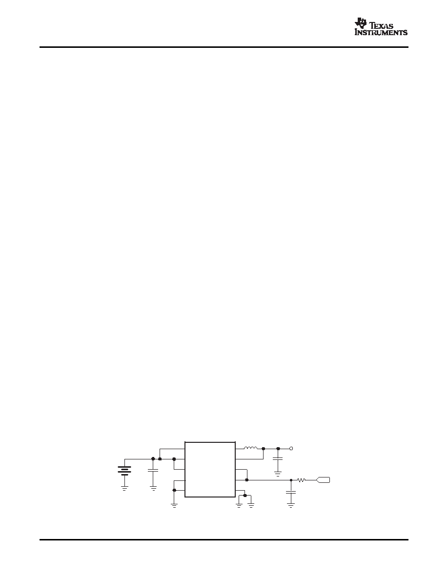
On TPS62300 and TPS62320 devices, the output voltage can be dynamically programmed to any voltage
between 0.6 V and VI (or 5.4 V whichever is lower) with an external DAC driving the ADJ and FB pins (see
Figure 33). The output voltage is then equal to A(PT) x V(DAC) with a Power Train amplification A(PT) typical = 1.5.
When the output voltage is driven low, the converter reduces its output quickly in forced PWM mode, boosting
the output energy back to the input. If the input is not connected to a low-impedance source capable of absorbing
the energy, the input voltage can rise above the absolute maximum voltage of the part and get damaged. The
faster VO is commanded low, the higher is the voltage spike at the input.
For best results, ramp the ADJ/FB signal as slow as the application allows. To avoid over-slew of the regulation
loop of the converter, avoid abrupt changes in output voltage of > 300 mV/
s (depending on V
I , output voltage
step size and L/C combination). If ramp control is unavailable, an RC filter can be inserted between the DAC
output and ADJ/FB pins to slow down the control signal.
Figure 33. Filtering the DAC Voltage
20
Copyright 2004–2007, Texas Instruments Incorporated
Product Folder Link(s): TPS62300, TPS62301, TPS62302 TPS62303, TPS62304, TPS62305, TPS62311, TPS62313,
相关PDF资料 |
PDF描述 |
|---|---|
| TPS3818G125DRVT | 1-CHANNEL POWER SUPPLY SUPPORT CKT, PDSO6 |
| TPS2223APWPG4 | 3-CHANNEL POWER SUPPLY SUPPORT CKT, PDSO24 |
| TL2842DRE4-8 | 1 A SWITCHING REGULATOR, 500 kHz SWITCHING FREQ-MAX, PDSO8 |
| TC151B4622EOA723 | 0.25 A SWITCHING REGULATOR, 50 kHz SWITCHING FREQ-MAX, PDSO8 |
| TC161B4316EOA713 | 0.25 A SWITCHING REGULATOR, 100 kHz SWITCHING FREQ-MAX, PDSO8 |
相关代理商/技术参数 |
参数描述 |
|---|---|
| TPS62305DRCRG4 | 功能描述:直流/直流开关调节器 1.875V 500-mA 3-MHz Step-Down Converter RoHS:否 制造商:International Rectifier 最大输入电压:21 V 开关频率:1.5 MHz 输出电压:0.5 V to 0.86 V 输出电流:4 A 输出端数量: 最大工作温度: 安装风格:SMD/SMT 封装 / 箱体:PQFN 4 x 5 |
| TPS62305YZDR | 功能描述:直流/直流开关调节器 1.875V 500-mA 3-MHz Step-Down Converter RoHS:否 制造商:International Rectifier 最大输入电压:21 V 开关频率:1.5 MHz 输出电压:0.5 V to 0.86 V 输出电流:4 A 输出端数量: 最大工作温度: 安装风格:SMD/SMT 封装 / 箱体:PQFN 4 x 5 |
| TPS62305YZDT | 功能描述:直流/直流开关调节器 1.875V 500-mA 3MHz Step-Down Converter RoHS:否 制造商:International Rectifier 最大输入电压:21 V 开关频率:1.5 MHz 输出电压:0.5 V to 0.86 V 输出电流:4 A 输出端数量: 最大工作温度: 安装风格:SMD/SMT 封装 / 箱体:PQFN 4 x 5 |
| TPS62311YZDR | 功能描述:直流/直流开关调节器 Adj 500-mA 3-MHz Step-Down Converter RoHS:否 制造商:International Rectifier 最大输入电压:21 V 开关频率:1.5 MHz 输出电压:0.5 V to 0.86 V 输出电流:4 A 输出端数量: 最大工作温度: 安装风格:SMD/SMT 封装 / 箱体:PQFN 4 x 5 |
| TPS62311YZDT | 功能描述:直流/直流开关调节器 Adj 500-mA 3-MHz Step-Down Converter RoHS:否 制造商:International Rectifier 最大输入电压:21 V 开关频率:1.5 MHz 输出电压:0.5 V to 0.86 V 输出电流:4 A 输出端数量: 最大工作温度: 安装风格:SMD/SMT 封装 / 箱体:PQFN 4 x 5 |
发布紧急采购,3分钟左右您将得到回复。