- 您现在的位置:买卖IC网 > PDF目录98285 > TPS65131RGETG4 (TEXAS INSTRUMENTS INC) 2.2 A SWITCHING REGULATOR, 1500 kHz SWITCHING FREQ-MAX, PQCC24 PDF资料下载
参数资料
| 型号: | TPS65131RGETG4 |
| 厂商: | TEXAS INSTRUMENTS INC |
| 元件分类: | 稳压器 |
| 英文描述: | 2.2 A SWITCHING REGULATOR, 1500 kHz SWITCHING FREQ-MAX, PQCC24 |
| 封装: | 4 X 4 MM, GREEN, PLASTIC, QFN-24 |
| 文件页数: | 18/34页 |
| 文件大小: | 785K |
| 代理商: | TPS65131RGETG4 |
第1页第2页第3页第4页第5页第6页第7页第8页第9页第10页第11页第12页第13页第14页第15页第16页第17页当前第18页第19页第20页第21页第22页第23页第24页第25页第26页第27页第28页第29页第30页第31页第32页第33页第34页
www.ti.com
Capacitor Selection
C
minP +
I
OUTP
V
POS *
V
IN
f
S
DVP
V
POS
(7)
C
minN +
I
OUTN
V
NEG
f
S
DVN
V
NEG *
V
IN
(8)
DVESRP + IOUTP
R
ESRP
(9)
DVESRN + IOUTN
R
ESRN
(10)
TPS65130, TPS65131
SLVS493B – MARCH 2004 – REVISED SEPTEMBER 2004
APPLICATION INFORMATION (continued)
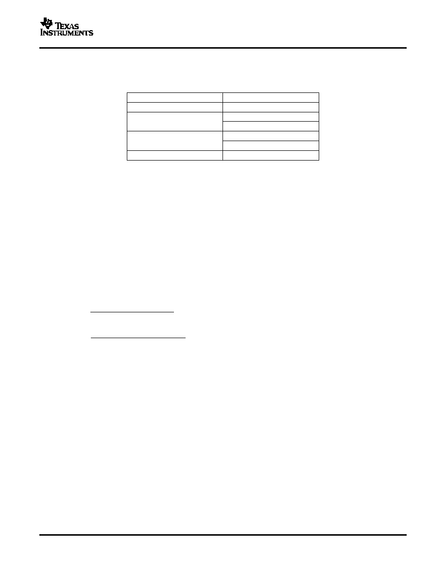
The following inductor series from different suppliers have been used with the TPS65130/1 converter:
List of Inductors
VENDOR
INDUCTOR SERIES
EPCOS
B8246284-G4
7447789XXX
Wurth Elektronik
744031XXX
VLF3010
TDK
VLF4012
Cooper Electronics Technologies
SD12
Input Capacitor
At least a 4.7-F input capacitor is recommended for the input of the boost converter (INP) and for the input of
the inverting converter (INN) to improve transient behavior of the regulators and EMI behavior of the total power
supply circuit. A ceramic capacitor or a tantalum capacitor with a smaller ceramic capacitor (100 nF) in parallel,
placed close to the input pins, is recommended.
Output Capacitors
One of the major parameters necessary to define the capacitance value of the output capacitor is the maximum
allowed output voltage ripple of the converter. This ripple is determined by two parameters of the capacitor, the
capacitance and the ESR. It is possible to calculate the minimum capacitance needed for the defined ripple,
supposing that the ESR is zero, by using Equation 7 for the boost converter output capacitor and Equation 8 for
the inverting converter output capacitor.
Parameter f is the switching frequency and
V is the maximum allowed ripple.
With a chosen ripple voltage in the range of 10 mV, a minimum capacitance of 12 F is needed. The total ripple
is larger due to the ESR of the output capacitor. This additional component of the ripple can be calculated using
Equation 9 for the boost converter and Equation 10 for the inverting converter.
An additional ripple of 2 mV is the result of using a typical ceramic capacitor with an ESR in a 10-m
range. The
total ripple is the sum of the ripple caused by the capacitance and the ripple caused by the ESR of the capacitor.
In this example, the total ripple is 10 mV. Additional ripple is caused by load transients. When the load current
increases rapidly, the output capacitor must provide the additional current until the inductor current has been
increased by the control loop by setting a higher on-time at the main switch (duty cycle). The higher duty cycle
results in longer inductor charging periods. But the rate of increase of the inductor current is also limited by the
inductance itself. When the load current decreases rapidly, the output capacitor needs to store the exessive
energy (stored in the inductor) until the regulator has decreased the inductor current by reducing the duty cycle.
The recommendation is to use higher capacitance values, as the aforegoing calculations show.
25
相关PDF资料 |
PDF描述 |
|---|---|
| TPS65130RGE | 0.9 A SWITCHING REGULATOR, 1500 kHz SWITCHING FREQ-MAX, PQCC24 |
| TPS65131RGERG4 | 2.2 A SWITCHING REGULATOR, 1500 kHz SWITCHING FREQ-MAX, PQCC24 |
| TPS65136RTE | 1.12 A SWITCHING REGULATOR, 1000 kHz SWITCHING FREQ-MAX, PQCC16 |
| TPS65136RTER | 1.12 A SWITCHING REGULATOR, 1000 kHz SWITCHING FREQ-MAX, PQCC16 |
| TPS65150PWPR | 3-CHANNEL POWER SUPPLY SUPPORT CKT, PDSO24 |
相关代理商/技术参数 |
参数描述 |
|---|---|
| TPS65131TRGERQ1 | 制造商:Texas Instruments 功能描述:IC REG BST INV ADJ 2A DL 24VQFN 制造商:Texas Instruments 功能描述:TPS65131TRGERQ1 |
| TPS65132A0YFFR | 制造商:Texas Instruments 功能描述:DUAL OUTPUT LCD BIAS |
| TPS65132AYFFR | 制造商:Texas Instruments 功能描述:DUAL OUTPUT LCD BIAS |
| TPS65132B0YFFR | 制造商:Texas Instruments 功能描述:DUAL OUTPUT LCD BIAS |
| TPS65132B2YFFR | 功能描述:DUAL OUTPUT LCD BIAS 15DSBGA 制造商:texas instruments 系列:- 包装:剪切带(CT) 零件状态:有效 显示类型:LCD,OLED 配置:- 接口:I2C 数字或字符:- 电流 - 电源:540μA 电压 - 电源:2.5 V ~ 5.5 V 工作温度:-40°C ~ 85°C 安装类型:表面贴装 封装/外壳:15-UFBGA,DSBGA 供应商器件封装:15-DSBGA 标准包装:1 |
发布紧急采购,3分钟左右您将得到回复。