- 您现在的位置:买卖IC网 > PDF目录69522 > TPS65140PWPG4 (TEXAS INSTRUMENTS INC) 2.6 A SWITCHING REGULATOR, 2100 kHz SWITCHING FREQ-MAX, PDSO24 PDF资料下载
参数资料
| 型号: | TPS65140PWPG4 |
| 厂商: | TEXAS INSTRUMENTS INC |
| 元件分类: | 稳压器 |
| 英文描述: | 2.6 A SWITCHING REGULATOR, 2100 kHz SWITCHING FREQ-MAX, PDSO24 |
| 封装: | GREEN, PLASTIC, HTSSOP-24 |
| 文件页数: | 2/31页 |
| 文件大小: | 1391K |
| 代理商: | TPS65140PWPG4 |
第1页当前第2页第3页第4页第5页第6页第7页第8页第9页第10页第11页第12页第13页第14页第15页第16页第17页第18页第19页第20页第21页第22页第23页第24页第25页第26页第27页第28页第29页第30页第31页
www.ti.com
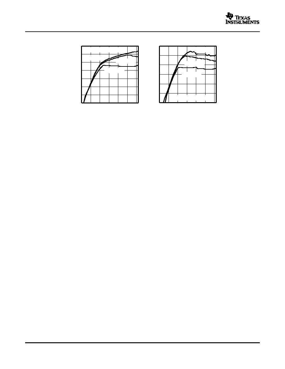
0
0.02
0.04
0.06
0.08
0.10
0.12
0.14
9
10
11
12
13
14
15
Vo1 Output Voltage V
Output
Current
A
I O
Vo3 = 18 V (Doubler Mode)
TA = 25°C
TA = 85°C
TA = 40°C
0
0.02
0.04
0.06
0.08
0.10
0.12
9
10
11
12
13
14
15
Vo1 Output Voltage V
Output
Current
A
I O
Vo3 = 28 V (Tripler Mode)
TA = 25°C
TA = 85°C
TA = 40°C
DETAILED DESCRIPTION
Main Boost Converter
Power-Good Output
Enable and Power-On Sequencing (EN, ENR)
SLVS497C – SEPTEMBER 2003 – REVISED APRIL 2006
VO3 MAXIMUM LOAD CURRENT
Figure 13.
Figure 14.
The TPS6514x series consists of a main boost converter operating with a fixed switching frequency of 1.6 MHz
to allow for small external components. The boost converter output voltage VO1 is also the input voltage,
connected via the pin SUP, for the positive and negative charge pump. The linear regulator controller is
independent from this system with its own enable pin. This allows the linear regulator controller to continue to
operate while the other supply rails are disabled or in shutdown due to a fault condition on one of their outputs.
Refer to the functional block diagram for more information.
The main boost converter operates with PWM and a fixed switching frequency of 1.6 MHz. The converter uses a
unique fast response, voltage mode controller scheme with input voltage feedforward. This achieves excellent
line and load regulation (0.2% A load regulation typical) and allows the use of small external components. To
add higher flexibility to the selection of external component values, the device uses external loop compensation.
Although the boost converter looks like a nonsynchronous boost converter topology operating in discontinuous
mode at light load, the TPS6514x series maintains continuous conduction even at light load currents. This is
accoplished using the Virtual Synchronous Converter Technology for improved load transient response. This
architecture uses an external Schottky diode and an integrated MOSFET in parallel connected between SW and
SUP (see the functional block diagram). The integrated MOSFET Q2 allows the inductor current to become
negative at light load conditions. For this purpose, a small integrated P-channel MOSFET with typically 10
rDS(on) is sufficient. When the inductor current is positive, the external Schottky diode with the lower forward
voltage conducts the current. This causes the converter to operate with a fixed frequency in continuous
conduction mode over the entire load current range. This avoids the ringing on the switch pin as seen with a
standard nonsynchronous boost converter and allows a simpler compensation for the boost converter.
The TPS6514x sereis has an open-drain power-good output with a maximum sink capability of 1 mA. The
power-good output goes high as soon as the main boost converter VO1 and the negative and the positive charge
pumps are within regulation. The power-good output goes low as soon as one of the outputs is out of regulation.
In this case, the device goes into shutdown at the same time. See the electrical characteristics table for the
power-good thresholds.
The device has two enable pins. These pins should be terminated and not left floating to prevent faulty
operation. Pulling the enable pin (EN) high enables the device and starts the power-on sequencing with the main
boost converter VO1 coming up first, then the negative and positive charge pump. The linear regulator has an
independent enable pin (ENR). Pulling this pin low disables the regulator, and pulling this pin high enables this
regulator.
If the enable pin (EN) is pulled high, the device starts its power-on sequencing. The main boost converter starts
10
相关PDF资料 |
PDF描述 |
|---|---|
| TPS65160PWPG4 | 4.2 A SWITCHING REGULATOR, 900 kHz SWITCHING FREQ-MAX, PDSO28 |
| TPS65160PWPR | 4.2 A SWITCHING REGULATOR, 900 kHz SWITCHING FREQ-MAX, PDSO28 |
| TPS65163RGZR | 4.2 A SWITCHING REGULATOR, 900 kHz SWITCHING FREQ-MAX, PQCC48 |
| TPS65185RGZR | 1-CHANNEL POWER SUPPLY SUPPORT CKT, PQCC48 |
| TPS65230A2DCA | 2-CHANNEL POWER SUPPLY SUPPORT CKT, PDSO48 |
相关代理商/技术参数 |
参数描述 |
|---|---|
| TPS65140PWPR | 功能描述:LCD 驱动器 Trp-Ch 2.1-A Swit Boost Converter RoHS:否 制造商:Maxim Integrated 数位数量:4.5 片段数量:30 最大时钟频率:19 KHz 工作电源电压:3 V to 3.6 V 最大工作温度:+ 85 C 最小工作温度:- 20 C 封装 / 箱体:PDIP-40 封装:Tube |
| TPS65140PWPRG4 | 功能描述:LCD 驱动器 Trp-Ch 2.1-A Swit Boost Converter RoHS:否 制造商:Maxim Integrated 数位数量:4.5 片段数量:30 最大时钟频率:19 KHz 工作电源电压:3 V to 3.6 V 最大工作温度:+ 85 C 最小工作温度:- 20 C 封装 / 箱体:PDIP-40 封装:Tube |
| TPS65140RGER | 功能描述:LCD 驱动器 Trp-Ch 2.1-A Swit Boost Converter RoHS:否 制造商:Maxim Integrated 数位数量:4.5 片段数量:30 最大时钟频率:19 KHz 工作电源电压:3 V to 3.6 V 最大工作温度:+ 85 C 最小工作温度:- 20 C 封装 / 箱体:PDIP-40 封装:Tube |
| TPS65140RGERG4 | 功能描述:LCD 驱动器 Trp-Ch 2.1-A Swit Boost Converter RoHS:否 制造商:Maxim Integrated 数位数量:4.5 片段数量:30 最大时钟频率:19 KHz 工作电源电压:3 V to 3.6 V 最大工作温度:+ 85 C 最小工作温度:- 20 C 封装 / 箱体:PDIP-40 封装:Tube |
| TPS65141PWP | 功能描述:LCD 驱动器 5V/1.6A(I/O) 4-CH Multi-Converter RoHS:否 制造商:Maxim Integrated 数位数量:4.5 片段数量:30 最大时钟频率:19 KHz 工作电源电压:3 V to 3.6 V 最大工作温度:+ 85 C 最小工作温度:- 20 C 封装 / 箱体:PDIP-40 封装:Tube |
发布紧急采购,3分钟左右您将得到回复。