- 您现在的位置:买卖IC网 > PDF目录297614 > TPSV227M016R-MR CAP. 220UF MINIREEL 100PCS PDF资料下载
参数资料
| 型号: | TPSV227M016R-MR |
| 英文描述: | CAP. 220UF MINIREEL 100PCS |
| 中文描述: | 第。 220UF MINIREEL 100片 |
| 文件页数: | 1/7页 |
| 文件大小: | 0K |
| 代理商: | TPSV227M016R-MR |
11
TPS Series
Low ESR
TPS
Type
C
Case Size
See table above
107
Capacitor Code
pF code: 1st two
digits represent
significant figures,
3rd digit represents
multiplier (number of
zeros to follow)
M
Tolerance
K=±10%
M=±20%
010
Rated DC Voltage
006=6.3Vdc
010=10Vdc
016=16Vdc
020=20Vdc
025=25Vdc
035=35Vdc
050=50Vdc
R
Packaging
See Tape and Reel
Packaging
R=7" T/R
S=13" T/R
(see page 47)
100
Maximum ESR in
Milliohms
See note below
HOW TO ORDER
The
TPS
surface
mount
products
have inherently low ESR (equivalent series
resistance) and are capable of higher
ripple current handling, producing lower
ripple voltages, less power and heat
dissipation than standard product for the
most efficient use of circuit power. TPS
has been designed, manufactured, and
preconditioned for optimum performance
in typical power supply applications. By
combining the latest improvements in
tantalum powder technology, improved
manufacturing processes, and applica-
tion specific preconditioning tests, AVX is
able to provide a technologically superior
alternative to the standard range.
NOTE: The EIA & CECC standards for low ESR Solid Tantalum Capacitors
allow an ESR movement to 1.25 times catalog limit post mounting.
Technical Data:
All technical data relate to an ambient temperature of +25°C
Capacitance Range:
1.0F to 470F
Capacitance Tolerance:
±10%; ±20%
Rated Voltage (V
R)
+85°C:
6.3
10
16
20
25
35
50
Category Voltage (V
C)
+125°C:
4
7
10
13
17
23
33
Surge Voltage (V
S)
+85°C:
8
13
20
26
32
46
65
Surge Voltage (V
S)
+125°C:
5
8
12
16
20
28
40
Temperature Range:
-55°C to +125°C
Environmental Classification:
55/125/56 (IEC 68-2)
Reliability:
1% per 1000 hours at 85°C with 0.1
/V series impedance, 60% confidence level
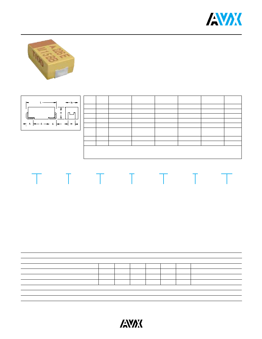
TECHNICAL SPECIFICATIONS
CASE DIMENSIONS: millimeters (inches)
Code
EIA
L±0.2 (0.008)
W+0.2 (0.008)
H+0.2 (0.008)
W
1±0.2 (0.008)
A+0.3 (0.012)
S Min.
Code
-0.1 (0.004)
-0.2 (0.008)
A
3216
3.2 (0.126)
1.6 (0.063)
1.2 (0.047)
0.8 (0.031)
1.1 (0.043)
B
3528
3.5 (0.138)
2.8 (0.110)
1.9 (0.075)
2.2 (0.087)
0.8 (0.031)
1.4 (0.055)
C
6032
6.0 (0.236)
3.2 (0.126)
2.6 (0.102)
2.2 (0.087)
1.3 (0.051)
2.9 (0.114)
D
7343
7.3 (0.287)
4.3 (0.169)
2.9 (0.114)
2.4 (0.094)
1.3 (0.051)
4.4 (0.173)
E
7343H
7.3 (0.287)
4.3 (0.169)
4.1 (0.162)
2.4 (0.094)
1.3 (0.051)
4.4 (0.173)
V
7361
7.3 (0.287)
6.1 (0.240)
3.45 ±0.3
3.1 (0.120)
1.4 (0.055)
4.4 (0.173)
(0.136±0.012)
W*
6032L
6.0 (0.236)
3.2 (0.126)
1.5 (0.059) max.
2.2 (0.087)
1.3 (0.051)
2.9 (0.114)
Y**
7343L
7.3 (0.287)
4.3 (0.169)
2.0 (0.079) max.
2.4 (0.094)
1.3 (0.051)
4.4 (0.173)
W1 dimension applies to the termination width for A dimensional area only.
* Low Profile Version of C Case (max. height 1.5mm)
** Low Profile Version of D Case (max. height 2mm)
For part marking see pages 12 & 48
相关PDF资料 |
PDF描述 |
|---|---|
| TPSV477M006R-MR | CAP. 470UF MINIREEL 100PCS |
| TPSMP-0309 | SMPS Controller |
| TPSMP-0311 | SMPS Controller |
| TPSMP-1500 | SMPS Controller |
| TPSMP-1501 | SMPS Controller |
相关代理商/技术参数 |
参数描述 |
|---|---|
| TPSV227M016S0075 | 功能描述:钽质电容器-固体SMD 16volts 220uF 20% RoHS:否 制造商:AVX 电容:100 uF 电压额定值:20 V ESR: 容差:10 % 外壳代码 - in:2917 外壳代码 - mm:7343 高度:4.1 mm 制造商库存号:E Case 工作温度范围:- 55 C to + 125 C 系列:TBM 产品:Tantalum Solid Low ESR Commercial Grade 封装:Bulk |
| TPSV227M016S0150 | 制造商:AVX Corporation 功能描述: |
| TPSV227M016Y0050 | 功能描述:钽质电容器-固体SMD 16volts 220uF 20% RoHS:否 制造商:AVX 电容:100 uF 电压额定值:20 V ESR: 容差:10 % 外壳代码 - in:2917 外壳代码 - mm:7343 高度:4.1 mm 制造商库存号:E Case 工作温度范围:- 55 C to + 125 C 系列:TBM 产品:Tantalum Solid Low ESR Commercial Grade 封装:Bulk |
| TPSV3360350200 | 制造商:AVX 制造商全称:AVX Corporation 功能描述:Low ESR series of robust Mn02 solid electrolyte capacitors |
| TPSV336K035R0200 | 功能描述:钽质电容器-固体SMD 35V 33uF 10% Tol. 200 ESR RoHS:否 制造商:AVX 电容:100 uF 电压额定值:20 V ESR: 容差:10 % 外壳代码 - in:2917 外壳代码 - mm:7343 高度:4.1 mm 制造商库存号:E Case 工作温度范围:- 55 C to + 125 C 系列:TBM 产品:Tantalum Solid Low ESR Commercial Grade 封装:Bulk |
发布紧急采购,3分钟左右您将得到回复。