- 您现在的位置:买卖IC网 > PDF目录66322 > TS2509CSRL SWITCHING REGULATOR, 600 kHz SWITCHING FREQ-MAX, PDSO8 PDF资料下载
参数资料
| 型号: | TS2509CSRL |
| 元件分类: | 稳压器 |
| 英文描述: | SWITCHING REGULATOR, 600 kHz SWITCHING FREQ-MAX, PDSO8 |
| 封装: | ROHS COMPLIANT, SOP-8 |
| 文件页数: | 5/9页 |
| 文件大小: | 491K |
| 代理商: | TS2509CSRL |
TS2509
3A / 500KHz PWM Buck Converter
5/9
Version: A09
Function Descriptions (Continue)
Output Capacitor Selection
(EL CAP)
The output capacitor is required to filter the output and provide regulator loop stability. The important capacitor
parameters are; the 100KHz Equivalent Series Resistance (ESR), the RMS ripples current rating, voltage rating, and
capacitance value. For the output capacitor, the ESR value is the most important parameter. The ESR can be
calculated from the following formula.
VRIPPLE = IL x ESR = 0.4A x 110mΩ = 44mV
An aluminum electrolytic capacitor's ESR value is related to the capacitance and its voltage rating. In most case, higher
voltage electrolytic capacitors have lower ESR values. Most of the time, capacitors with much higher voltage ratings
may be needed to provide the low ESR values required for low output ripple voltage. It is recommended to replace this
low ESR capacitor by using a 330F low ESR values < 110mΩ
(MLCC)
A 33F MLCC or three 10uF MLCC capacitors for most applications is sufficient.
RDS(ON) Current Limiting
The current limit threshold is setting by the internal circuit.
VIN
4.6V~6V
6V~10V
10V~23V
ICL(MIN)
3A
3.8A
4.0A
IOUT(MAX)
2.5A
3A
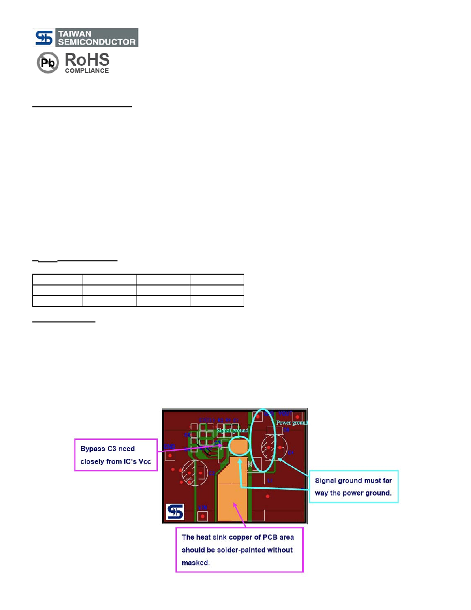
Layout Guidance
When laying out the PC board, the following suggestions should be taken to ensure proper operation of the TS2509.
These items are also illustrated graphically in below.
1. The power traces, including the PMOS Drain & Source trace, the Schottky and the C2 trace should be kept short,
direct and wide to allow large current flow.
2. Connect the C5 to the VCC & EN pins of the TS2509 as closely as possible to get good power filter effect.
3. Keep the switching node, away from the sensitive FB node.
4. Connect ground side of the C2 & D1 as closely as possible.
5. Connect PMOS Source and R3 as closely as possible.
6. Do not trace signal line under inductor.
相关PDF资料 |
PDF描述 |
|---|---|
| TS2576CM550RN | SWITCHING REGULATOR, 58 kHz SWITCHING FREQ-MAX, PSSO5 |
| TS2596CZ5C0 | SWITCHING REGULATOR, 173 kHz SWITCHING FREQ-MAX, SFM5 |
| TS2596CM5RN | SWITCHING REGULATOR, 173 kHz SWITCHING FREQ-MAX, PSSO5 |
| TS2596SCSRL | SWITCHING REGULATOR, 173 kHz SWITCHING FREQ-MAX, PDSO8 |
| TS3810CXCRF | 1-CHANNEL POWER SUPPLY SUPPORT CKT, PDSO3 |
相关代理商/技术参数 |
参数描述 |
|---|---|
| TS250A | 制造商:Black Box Corporation 功能描述:10/100/1000 COPPER TAP |
| TS250AE | 制造商:Black Box Corporation 功能描述:10/100/1000 COPPER TAP W/UK POWER CORD |
| TS250AE-W1 | 制造商:Black Box Corporation 功能描述:1 YEAR WARRANTY FOR TS250AE |
| TS250AE-W3 | 制造商:Black Box Corporation 功能描述:3 YEAR WARRANTY FOR TS250AE |
| TS250A-W1 | 制造商:Black Box Corporation 功能描述:1 YEAR WARRANTY FOR TS250A |
发布紧急采购,3分钟左右您将得到回复。