- 您现在的位置:买卖IC网 > PDF目录373702 > TS2951ACS (Taiwan Semiconductor Co., Ltd.) 5.0 AMP POSITIVE VOLTAGE REGULATOR PDF资料下载
参数资料
| 型号: | TS2951ACS |
| 厂商: | Taiwan Semiconductor Co., Ltd. |
| 元件分类: | 基准电压源/电流源 |
| 英文描述: | 5.0 AMP POSITIVE VOLTAGE REGULATOR |
| 中文描述: | 5.0放大器正电压稳压器 |
| 文件页数: | 3/6页 |
| 文件大小: | 134K |
| 代理商: | TS2951ACS |
TS2950-51 series
3-6
2003/12 rev. B
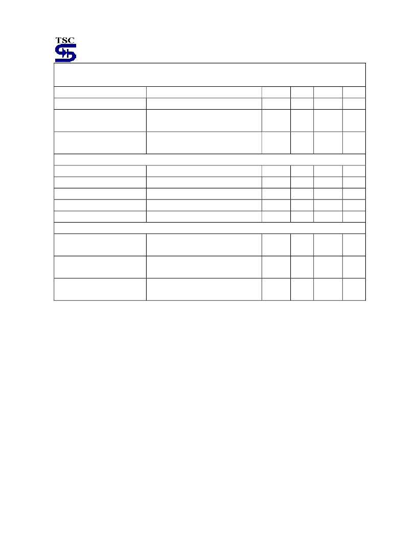
TS2951/A Electrical Characteristics
(continues)
(Vin= 15V, Ta= 25
o
C unless otherwise specified.)
Parameter
Test Conditions (note 2)
Min
Typ
Max
Unit
Feedback Pin Bias Current
--
20
40
nA
Reference Voltage Temperature
Coefficient
(Note 7)
--
20
--
ppm/
o
C
Feedback Pin Bias Current
Temperature Coefficient
--
0.1
--
nA/
o
C
Error Comparator
Output Leakage Current
V
OH
= 30V
--
0.01
1
uA
Output Low Voltage
Vin= 4.5V, I
OL
= 400uA
--
150
250
mV
Upper Threshold Voltage
(Note 8)
40
60
--
mV
Power Threshold Voltage
(Note 8)
--
75
95
mV
Hysteresis
(Note 8)
--
15
--
mV
Shutdown Input
Output Logic Voltage
Low (Regulator ON)
High(Regulator OFF)
--
2.0
1.3
1.3
0.7
--
V
Shut down Pin Current
Vs = 2.4V
Vs = 30V
--
30
450
50
600
uA
Regulator Output Current in
Shutdown
(Note 9)
--
3
10
uA
Note 1: Output voltage temperature coefficients defined as the worst case voltage change divided by the total
temperature range.
Note 2: Unless otherwise specified all limits guaranteed for T
j
= 25
o
C, Vin= 6V, I
L
= 100uA and C
L
= 100uF. Additional
conditions for the 8-pin versions are feedback tied to 5V, 3.3V & 3V tap output Sense (Vout = 5V, 3.3V & 3V) and
Vshutdown
≤
0.8V.
Note 3: Regulation is measured at constant junction temperature, using pulse testing with a low duty cycle. Changes in
output voltage due to heating effects are covered under the specification for thermal regulation.
Note 4: Line regulation for the TS2951 is tested at 85
o
C for I
L
= 1mA.For I
L
= 100uA and Tj= 125
o
C, line regulation is
guaranteed by design to 0.2%.
Note 5: Dropout Voltage is defined as the input to output differential at which the output voltage drops 100mV below its
nominal value measured at 1V differential at very low value of programmed output voltage, the minimum input
supply voltage of 2V (2.3V over temperature) must be taken in to account.
Note 6: Vref
≤
Vout
≤
(Vin-1V), 2.3
≤
Vin
≤
30V, 100uA
≤
I
L
≤
100mA, Tj
≤
Tj(max)
.
Note 7: reference voltage temperature coefficient is defined as the worst case voltage change divided by the total
temperature range.
Note 8: Comparator thresholds are expressed in terms of a voltage differential at the feedback terminal below the
nominal reference voltage measured at 6V input. To express these thresholds in terms of output voltage change,
multiply by the error amplifier gain= Vout / Vref = (R1+R2) / R2. For example, at a programmed output voltage of
5V, the Error output is guaranteed to go low when the output drops by 95 mV X 5V / 1.250 = 384mV. Thresholds
remain constant as a percent of Vout as Vout is varied with the dropout warning occurring at typically 5% below
nominal, 7.5% guaranteed.
相关PDF资料 |
PDF描述 |
|---|---|
| TS2951CS-3.0 | 5.0 AMP POSITIVE VOLTAGE REGULATOR |
| TS2951CS-3.3 | 5.0 AMP POSITIVE VOLTAGE REGULATOR |
| TS2N2222A | General Purpose NPN Transistor |
| TS2N2222ACXRF | General Purpose NPN Transistor |
| TS3-45A01 | 3-pole MCF |
相关代理商/技术参数 |
参数描述 |
|---|---|
| TS2951ACS-3.0 | 制造商:TSC 制造商全称:Taiwan Semiconductor Company, Ltd 功能描述:150mA Ultra Low Dropout Positive Voltage Regulator |
| TS2951ACS-3.3 | 制造商:TSC 制造商全称:Taiwan Semiconductor Company, Ltd 功能描述:150mA Ultra Low Dropout Positive Voltage Regulator |
| TS2951ACS-5.0 | 制造商:TSC 制造商全称:Taiwan Semiconductor Company, Ltd 功能描述:150mA Ultra Low Dropout Positive Voltage Regulator |
| TS2951ACS50 | 功能描述:低压差稳压器 - LDO 0.15A Ultra LDO 5.0v Vltg Reg RoHS:否 制造商:Texas Instruments 最大输入电压:36 V 输出电压:1.4 V to 20.5 V 回动电压(最大值):307 mV 输出电流:1 A 负载调节:0.3 % 输出端数量: 输出类型:Fixed 最大工作温度:+ 125 C 安装风格:SMD/SMT 封装 / 箱体:VQFN-20 |
| TS2951ACS50 RL | 制造商:SKMI/Taiwan 功能描述:LDO Regulator Pos 1.24V to 29V5V 0.15A 8-Pin SOP T/R |
发布紧急采购,3分钟左右您将得到回复。