- 您现在的位置:买卖IC网 > PDF目录373702 > TS34063 (Taiwan Semiconductor Co., Ltd.) Dc to Dc Converter Controller PDF资料下载
参数资料
| 型号: | TS34063 |
| 厂商: | Taiwan Semiconductor Co., Ltd. |
| 英文描述: | Dc to Dc Converter Controller |
| 中文描述: | 直流到直流转换器控制器 |
| 文件页数: | 2/8页 |
| 文件大小: | 115K |
| 代理商: | TS34063 |
TS34063
2-8
2003/12 rev. C
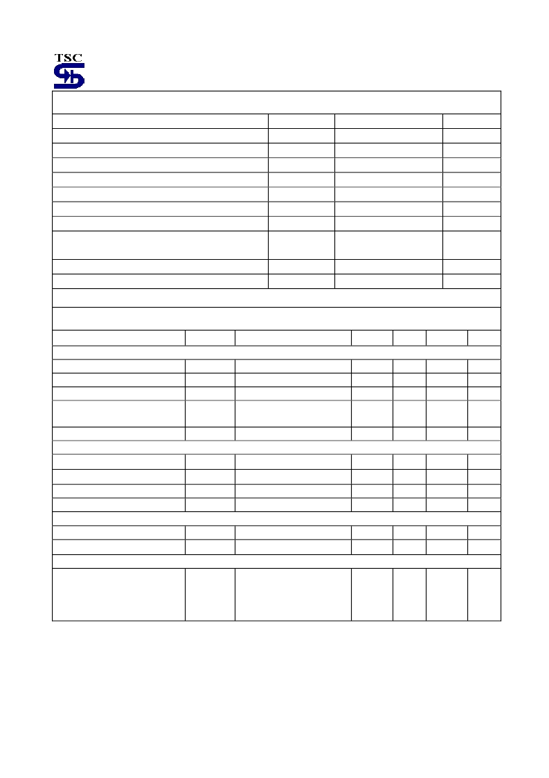
Absolute Maximum Rating
Supply Voltage
V
CC
V
FB
V
C(SW)
V
E(SW)
V
CE(SW)
Vc(driver)
40
V
Comparator Input Voltage Range
- 0.3 ~ 40
V
Switch Collector Output Voltage
40
V
Switch Emitter Voltage
40
V
Switch Collector to Emitter Voltage
40
V
Driver Collector Voltage
40
V
Driver Collector Current (note 1)
Ic(driver)
100
mA
Output Switching Current
I
SW
1.5
A
Power Dissipation DIP-8
SOP-8
Pd
1.0
0.5
W
Operating Junction Temperature Range
T
J
T
STG
-0 ~ +125
o
C
Storage Temperature Range
-65 ~ +150
o
C
Note: Maximum package power dissipation limits must be observed
Electrical Characteristics
(V
CC
=5V, Ta =25
o
C; unless otherwise specified.)
Parameter
Symbol
Test Conditions
Min
Typ
Max
Unit
Oscillator (OSC)
Frequency
Charge Current
Discharge Current
F
OSC
I
CHARGE
I
DISCHARGE
I
DISCHARGE
/ I
CHARGE
V
IPK(SENSE)
C
T
= 1nF, Vpin5= 0V
V
CC
= 5V ~ 40V
V
CC
= 5V ~ 40V
24
--
--
33
30
200
42
--
--
KHz
uA
uA
Discharge to Charge current ratio
Pin7 to Vcc
--
6.5
--
--
Current Limit Sense Voltage
Output switch (note1)
I
DISCHARGE
= I
CHARGE
250
--
350
mV
Saturation Voltage
V
CE(SAT)
I
SW
= 1A, pin1,8 connected)
--
1.0
1.3
V
Saturation Voltage
V
CE(SAT)
H
FE
I
C(OFF)
I
SW
= 1A, Id=50mA
I
SW
= 1A, Vce= 0.5V
Vce= 40V
--
0.45
0.7
V
DC current gain
Collector off-state current
Comparator
Threshold Voltae
--
--
75
0.01
--
--
uA
100
V
REF
RegLine
1.225
1.25
1.275
V
Line regulation
V
CC
= 3V ~ 40V
--
--
6
mV
Total device
Supply Current
I
CC
V
CC
= 5V ~ 40V, C
T
= 1nF,
pin7=Vcc, pin5>Vth,
pin2=Gnd, remaining pins
open
--
3
5
mA
Note: 1. Low duty cycle pulse techniques are used during test to maintain junction temperature as close to ambient
temperature as possible
2. If the output switch is driven into hard saturation (non-Darlington configuration) at low switch currents (<=300mA)
and high driver currents (>=30mA), it may take up to 2uS for it to come out of saturation. This condition will
shorten the off time at frequencies >= 30KHz, and is magnified at high temperature. This condition does not
occur with a Darlington configuration, since the output switch cannot saturate. If a non-Darlington configuration
is used, the following output drive condition is recommended:
Forced Bata of output switch:
Ic output / (Ic driver – 7mA*) >= 10
* The 100ohm resistor in the emitter of the driver divide requires about 7mA before the output switch conducts.
相关PDF资料 |
PDF描述 |
|---|---|
| TS34063CD | Dc to Dc Converter Controller |
| TS34063CS | Dc to Dc Converter Controller |
| TS34118 | Voice Switched Speakerphone Circuit |
| TS34118CD | Voice Switched Speakerphone Circuit |
| TS34118CS | Voice Switched Speakerphone Circuit |
相关代理商/技术参数 |
参数描述 |
|---|---|
| TS34063_07 | 制造商:TSC 制造商全称:Taiwan Semiconductor Company, Ltd 功能描述:Dc to Dc Converter Controller |
| TS34063A | 制造商:TSC 制造商全称:Taiwan Semiconductor Company, Ltd 功能描述:Dc to Dc Converter Controller |
| TS34063ACD | 制造商:TSC 制造商全称:Taiwan Semiconductor Company, Ltd 功能描述:Dc to Dc Converter Controller |
| TS34063ACS | 制造商:TSC 制造商全称:Taiwan Semiconductor Company, Ltd 功能描述:Dc to Dc Converter Controller |
| TS34063CD | 功能描述:开关变换器、稳压器与控制器 1.5 Amp 40 Volt Converter/Controller RoHS:否 制造商:Texas Instruments 输出电压:1.2 V to 10 V 输出电流:300 mA 输出功率: 输入电压:3 V to 17 V 开关频率:1 MHz 工作温度范围: 安装风格:SMD/SMT 封装 / 箱体:WSON-8 封装:Reel |
发布紧急采购,3分钟左右您将得到回复。