- 您现在的位置:买卖IC网 > PDF目录373702 > TS34118 (Taiwan Semiconductor Co., Ltd.) Voice Switched Speakerphone Circuit PDF资料下载
参数资料
| 型号: | TS34118 |
| 厂商: | Taiwan Semiconductor Co., Ltd. |
| 英文描述: | Voice Switched Speakerphone Circuit |
| 中文描述: | 语音开关扬声器电路 |
| 文件页数: | 13/20页 |
| 文件大小: | 328K |
| 代理商: | TS34118 |
TS34118
13-20
2004/09 rev. B
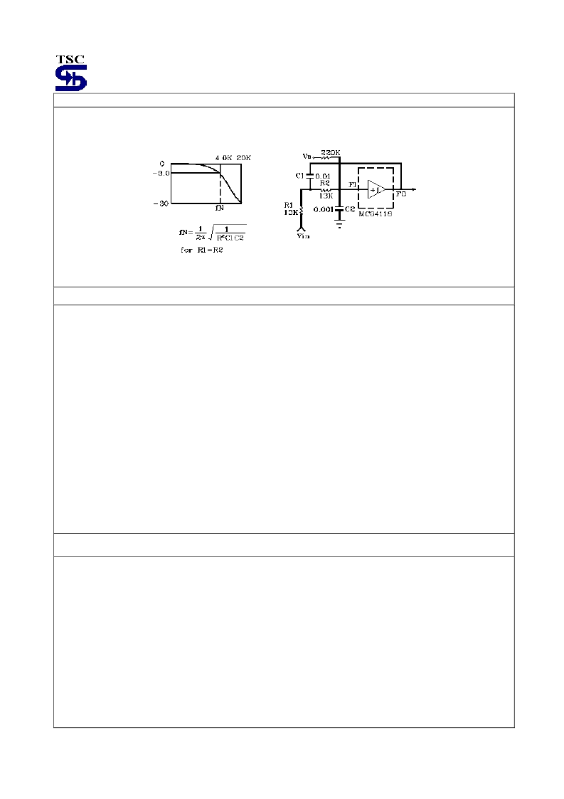
Filter
As a low pass filter (Figure 9), it can be used to roll off the high end frequencies in the receive circuit, which aids in
protecting against acoustic feedback problems. With an appropriate choice of an input coupling capacitor to the low
pass filter is formed
Figure 9. Low Pass Filter
Power Supply, V
B
, and Chip Disable
The power supply voltage at Vcc (pin 4) is to be between 3.5 and 6.5 volts for normal operation, with reduced operation
possible down to 2.8 volts. The power supply current is shown in Figure 18 for both the power-up and power-down
mode.
The output voltage at V
B
(pin 15) is
≈
(Vcc-0.7)/2, and provides the ac ground for the system. The output impedance at
V
B
is
≈
400
and in conjunction with the external capacitor at V
B
, forms a low pass filter for power supply rejection with
different capacitors. The choice of capacitor is application dependent base on whether the circuit is powered by the
telephone line or a power supply.
Since V
B
biases the microphone and hybrid amplifiers, the amount of supply rejection at their outputs is directly related
to the rejection at V
B
, as well as their respective gains. Depicts this graphically.
The Chip Disable (pin 3) permits powering down the IC to conserve power and/or for muting purposes. With CD
≤
0.8
volts, normal operation is in effect. With CD
≥
2.0 volts and
≤
Vcc, the IC is powered down. In the powered down mode,
the microphone and the hybrid amplifiers are disable, and their outputs go to a high impedance state. Additionally, the
bias is removed from the level detectors. The bias is not removed from the filter (pins 1,2). The attenuators (pin 8,9, 21,
22), or from pin 13,14, and 15 (the attenuators are disabled, however, and will not pass a signal). The input impedance
at CD is typically 90K
, has a threshold of
≈
1.5 volts, and the voltage at this pin must be kept within the range of
ground and Vcc . If CD is not used, the pin should be grounded.
Switching Time
The switching time of the TS34118 circuit is dominated by the components at C
T
(pin 14, refer to Figure 6), and
secondarily by the capacitors at the level detector outputs (RLO1, RLO2, TLO1, TLO2).
The time to switch to receive or to transmit from idle is determined by the capacitor at C
T
, together with the internal
current sources (refer to Figure 6). The switching time is:
T=
V × C
T
/ I
For the typical cause where
V=240mV, I=60μA. And C
T
is 50μF,
T=20ms. If the circuit switches directly from receive
to transmit (or vice-versa), the total switching time would be 40ms.
The switching time from either receive or transmit to idle depends on which type of idle mode is in effect. If the circuit is
going to “fast idle”, the time constant is determined by the C
T
capacitor, and the internal 2.0K
resistor (Figure 6). With
C
T
= 5.0μF, the time constant is
≈
30ms (for 95% change). Fast idle is an infrequent occurrence, however, occurring
when both speakers are talking and competing for control of the circuit. The switching time from idle back to either
transmit or receive is described above.
相关PDF资料 |
PDF描述 |
|---|---|
| TS34118CD | Voice Switched Speakerphone Circuit |
| TS34118CS | Voice Switched Speakerphone Circuit |
| TS34119 | Low Power Audio Amplifier |
| TS34119CD | Low Power Audio Amplifier |
| TS34119CS | Low Power Audio Amplifier |
相关代理商/技术参数 |
参数描述 |
|---|---|
| TS34118_1 | 制造商:TSC 制造商全称:Taiwan Semiconductor Company, Ltd 功能描述:Voice Switched Speakerphone Circuit |
| TS34118_13 | 制造商:TSC 制造商全称:Taiwan Semiconductor Company, Ltd 功能描述:Voice Switched Speakerphone Circuit Chip disable for active/standby operation |
| TS34118CD | 制造商:TSC 制造商全称:Taiwan Semiconductor Company, Ltd 功能描述:Voice Switched Speakerphone Circuit |
| TS34118CD28C4 | 制造商:TSC 制造商全称:Taiwan Semiconductor Company, Ltd 功能描述:Voice Switched Speakerphone Circuit |
| TS34118CS | 制造商:TSC 制造商全称:Taiwan Semiconductor Company, Ltd 功能描述:Voice Switched Speakerphone Circuit |
发布紧急采购,3分钟左右您将得到回复。