- 您现在的位置:买卖IC网 > PDF目录199476 > TS87C51RD2-VCLB 8-BIT MICROCONTROLLER PDF资料下载
参数资料
| 型号: | TS87C51RD2-VCLB |
| 元件分类: | 8位微控制器 |
| 英文描述: | 8-BIT MICROCONTROLLER |
| 中文描述: | 8位微控制器 |
| 文件页数: | 35/74页 |
| 文件大小: | 689K |
| 代理商: | TS87C51RD2-VCLB |
第1页第2页第3页第4页第5页第6页第7页第8页第9页第10页第11页第12页第13页第14页第15页第16页第17页第18页第19页第20页第21页第22页第23页第24页第25页第26页第27页第28页第29页第30页第31页第32页第33页第34页当前第35页第36页第37页第38页第39页第40页第41页第42页第43页第44页第45页第46页第47页第48页第49页第50页第51页第52页第53页第54页第55页第56页第57页第58页第59页第60页第61页第62页第63页第64页第65页第66页第67页第68页第69页第70页第71页第72页第73页第74页
40
Rev. C - 06 March, 2001
TS80C51RA2/RD2
TS83C51RB2/RC2/RD2
TS87C51RB2/RC2/RD2
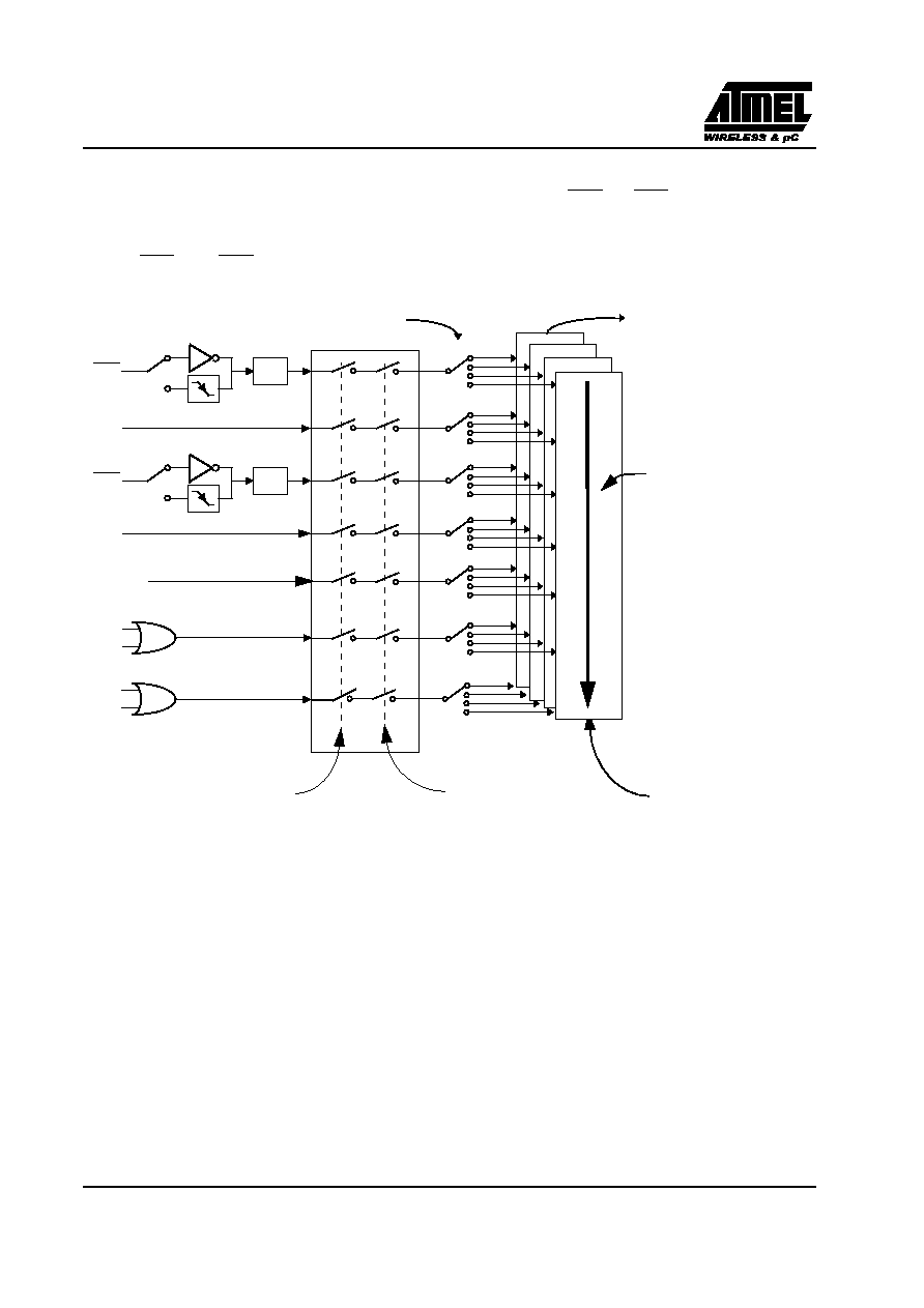
6.7. Interrupt System
The TS80C51Rx2 has a total of 7 interrupt vectors: two external interrupts (INT0 and INT1), three timer interrupts
(timers 0, 1 and 2), the serial port interrupt and the PCA global interrupt. These interrupts are shown in Figure 16.
WARNING: Note that in the first version of RC devices, the PCA interrupt is in the lowest priority. Thus the
order in INT0, TF0, INT1, TF1, RI or TI, TF2 or EXF2, PCA.
Figure 16. Interrupt Control System
Each of the interrupt sources can be individually enabled or disabled by setting or clearing a bit in the Interrupt
Enable register (See Table 19.). This register also contains a global disable bit, which must be cleared to disable
all interrupts at once.
Each interrupt source can also be individually programmed to one out of four priority levels by setting or clearing
a bit in the Interrupt Priority register (See Table 20.) and in the Interrupt Priority High register (See Table 21.).
shows the bit values and priority levels associated with each combination.
The PCA interrupt vector is located at address 0033H. All other vector addresses are the same as standard C52 devices.
IE1
0
3
High priority
interrupt
Interrupt
polling
sequence, decreasing
from high to low priority
Low priority
interrupt
Global Disable
Individual Enable
EXF2
TF2
TI
RI
TF0
INT0
INT1
TF1
IPH, IP
IE0
0
3
0
3
0
3
0
3
0
3
0
3
PCA IT
相关PDF资料 |
PDF描述 |
|---|---|
| TS87C51RD2-VCLD | 8-BIT MICROCONTROLLER |
| TS87C51RD2-VCLR | 8-BIT MICROCONTROLLER |
| TS87C51RD2-VCMB | 8-BIT MICROCONTROLLER |
| TS87C51RD2-VCMD | 8-BIT MICROCONTROLLER |
| TS87C51RD2-VIAD | 8-BIT MICROCONTROLLER |
相关代理商/技术参数 |
参数描述 |
|---|---|
| TS87C51RD2-VCLD | 制造商:未知厂家 制造商全称:未知厂家 功能描述:8-Bit Microcontroller |
| TS87C51RD2-VCLR | 制造商:未知厂家 制造商全称:未知厂家 功能描述:8-Bit Microcontroller |
| TS87C51RD2-VCM | 制造商:ATMEL 制造商全称:ATMEL Corporation 功能描述:High Performance 8-bit Microcontroller |
| TS87C51RD2-VCMB | 制造商:未知厂家 制造商全称:未知厂家 功能描述:8-Bit Microcontroller |
| TS87C51RD2-VCMD | 制造商:未知厂家 制造商全称:未知厂家 功能描述:8-Bit Microcontroller |
发布紧急采购,3分钟左右您将得到回复。