- 您现在的位置:买卖IC网 > Datasheet目录57 > TSL1410R (AMS-TAOS USA Inc)IC LINEAR SENSOR ARRAY 1280X1 Datasheet资料下载
参数资料
| 型号: | TSL1410R |
| 厂商: | AMS-TAOS USA Inc |
| 文件页数: | 3/13页 |
| 文件大小: | 629K |
| 描述: | IC LINEAR SENSOR ARRAY 1280X1 |
| 标准包装: | 20 |
| 系列: | * |
| 其它名称: | TSL1410-R |
TSL1410R
1280 ?1 LINEAR SENSOR ARRAY WITH HOLD
TAOS043E APRIL 2007
2
r
r
Copyright E 2007, TAOS Inc.
The LUMENOLOGY r Company
www.taosinc.com
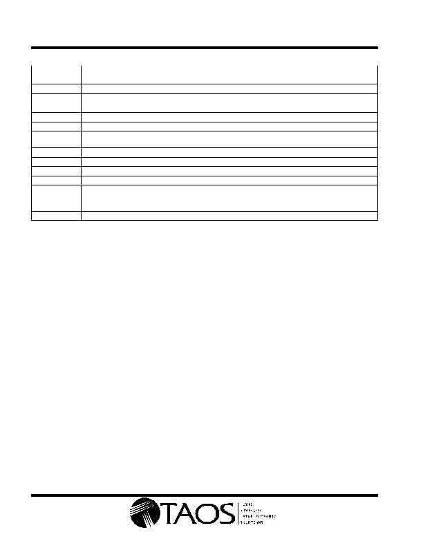
Terminal Functions
TERMINAL
NAME
NO.
I/O
DESCRIPTION
AO1
6
O
Analog output, section 1.
AO2
12
O
Analog output, section 2.
CLK1
4
I
Clock, section 1. CLK1 controls charge transfer, pixel output, and reset.
CLK2
10
I
Clock, section 2. CLK2 controls charge transfer, pixel output, and reset.
GND
5
Ground (substrate). All voltages are referenced to GND.
HOLD1
3
I
Hold signal. HOLD1 shifts pixel data to parallel buffer. HOLD1 is normally connected to SI1 and HOLD2 in
serial mode and to SI1 in parallel mode.
HOLD2
9
I
Hold signal. HOLD2 shifts pixel data to parallel buffer. HOLD2 is normally connected to SI2 in parallel mode.
SI1
2
I
Serial input (section 1). SI1 defines the start of the data-out sequence.
SI2
8
I
Serial input (section 2). SI2 defines the start of the data-out sequence.
SO1
7
O
Serial output (section 1). SO1 provides a signal to drive the SI2 input in serial mode.
SO2
11
O
Serial output (section 2). SO2 provides a signal to drive the SI input of another device for cascading or as an
end-of-data indication.
V
DD
13
Supply voltage for both analog and digital circuitry.
V
PP
1
Normally grounded.
Detailed Description
The sensor consists of 1280 photodiodes, called pixels, arranged in a linear array. Light energy impinging on a pixel
generates photocurrent that is then integrated by the active integration circuitry associated with that pixel.
During the integration period, a sampling capacitor connects to the output of the integrator through an analog switch. The
amount of charge accumulated at each pixel is directly proportional to the light intensity on that pixel and the integration time.
The output and reset of the integrators are controlled by a 640-bit shift register and reset logic. An output cycle is initiated
by clocking in a logic 1 on SI. Another signal, called HOLD, is generated from the rising edge of SI1 when SI1 and HOLD1
are connected together. This causes all 640 sampling capacitors to be disconnected from their respective integrators and
starts an integrator reset period. As the SI pulse is clocked through the shift register, the charge stored on the sampling
capacitors is sequentially connected to a charge-coupled output amplifier that generates a voltage on analog output AO.
The integrator reset period ends 18 clock cycles after the SI pulse is clocked in. Then the next integration period begins.
On the 640
th
clock rising edge, the SI pulse is clocked out on the SO1 pin (section 1) and becomes the SI pulse for section
2 (when SO1 is connected to SI2). The rising edge of the 641
st
clock cycle terminates the SO1 pulse, and returns the analog
output AO of section 1 to high-impedance state. Similarly, SO2 is clocked out on the 1280
th
clock pulse. Note that a 1281
st
clock pulse is needed to terminate the SO2 pulse and return AO of Section 2 to the high-impedance state. If a minimum
integration time is desired, the next SI pulse may be presented after a minimum delay of t
qt
(pixel charge transfer
time) after the 1281
st
clock pulse. Sections 1 and 2 may be operated in parallel or in serial fashion.
AO is an op amp-type output that does not require an external pull-down resistor. This design allows a rail-to-rail
output voltage swing. With V
DD
= 5 V, the output is nominally 0 V for no light input, 2 V for normal white level, and 4.8 V
for saturation light level. When the device is not in the output phase, AO is in a high-impedance state.
The voltage developed at analog output (AO) is given by:
V
out
= V
drk
+ (R
e
) (E
e
)(t
int
)
where:
V
out
is the analog output voltage for white condition
V
drk
is the analog output voltage for dark condition
R
e
is the device responsivity for a given wavelength of light given in V/(糐/cm
2
)
E
e
is the incident irradiance in 糤/cm
2
t
int
is integration time in seconds
A 0.1 糉 bypass capacitor should be connected between V
DD
and ground as close as possible to the device.
相关PDF资料 |
PDF描述 |
|---|---|
| TSL1412S | IC LINEAR SENSOR ARRAY 1536X1 |
| TSL2014 | IC LINEAR SENSOR ARRAY 896X1 |
| TSL202R | IC LINEAR SENSOR ARRAY 128X1 |
| TSL208R | IC LINEAR SENSOR ARRAY 512X1 |
| TSL210 | IC LINEAR SENSOR ARRAY 640X1 |
相关代理商/技术参数 |
参数描述 |
|---|---|
| TSL1412S | 功能描述:光学开关,专业型 Linear Array 400 DPI RoHS:否 制造商:ams 感应方式: 安装风格:Through Hole 封装:Tube |
| TSL14S | 功能描述:光频率和光电压 Light to Voltage Converter RoHS:否 制造商:ams 峰值波长:1000 nm 工作电源电压:5 V 最大工作温度:+ 85 C 最小工作温度:- 25 C 安装风格: 封装 / 箱体: |
| TSL14S-LF | 功能描述:光频率和光电压 Light to Voltage Converter RoHS:否 制造商:ams 峰值波长:1000 nm 工作电源电压:5 V 最大工作温度:+ 85 C 最小工作温度:- 25 C 安装风格: 封装 / 箱体: |
| TSL14SM-LF | 功能描述:光频率和光电压 Light to Voltage Converter RoHS:否 制造商:ams 峰值波长:1000 nm 工作电源电压:5 V 最大工作温度:+ 85 C 最小工作温度:- 25 C 安装风格: 封装 / 箱体: |
| TSL1LTE12L1F | 功能描述:电流传感电阻器 - SMD 1watt 0.0121ohm 1% RoHS:否 制造商:Vishay/Dale 电阻:10 mOhms 功率额定值:1 W 容差:1 % 外壳代码 - in:2512 外壳代码 - mm:6432 温度系数:75 PPM / C 系列:WSL 工作温度范围:- 65 C to + 170 C 产品:Power Metal Strip Resistors Low Value |
发布紧急采购,3分钟左右您将得到回复。