- 您现在的位置:买卖IC网 > PDF目录272834 > TSM101IN (STMICROELECTRONICS) SPECIALTY ANALOG CIRCUIT, PDIP8 PDF资料下载
参数资料
| 型号: | TSM101IN |
| 厂商: | STMICROELECTRONICS |
| 元件分类: | 模拟信号调理 |
| 英文描述: | SPECIALTY ANALOG CIRCUIT, PDIP8 |
| 封装: | PLASTIC, DIP-8 |
| 文件页数: | 11/13页 |
| 文件大小: | 387K |
| 代理商: | TSM101IN |
TSM101/A
7/13
If pin 2 is connected to ground, the internal current
source is enabled, the current measurement is
off-setted by a voltage equal to :
Vr4 = Io x R4 with Io = 1.4mA
This can be used to lower the charging current or
eventually to stop the charge, if Vr4 > Vr5
In our example, the current offset is equal to 700 -
200mA = 500mA, representing a voltage offset
Vr4 = 140mV across R4.
The following values are used on the application
board :
R5 = 4 *1.2 0.5W in parallel
R4 = 100
R2 = 1.2k
R3 = 220
R9 = short circuit
R1 = 10k
C2 = 100nF
C5 = 100nF
C1 = output capacitor of the SMPS
C4 = 10F
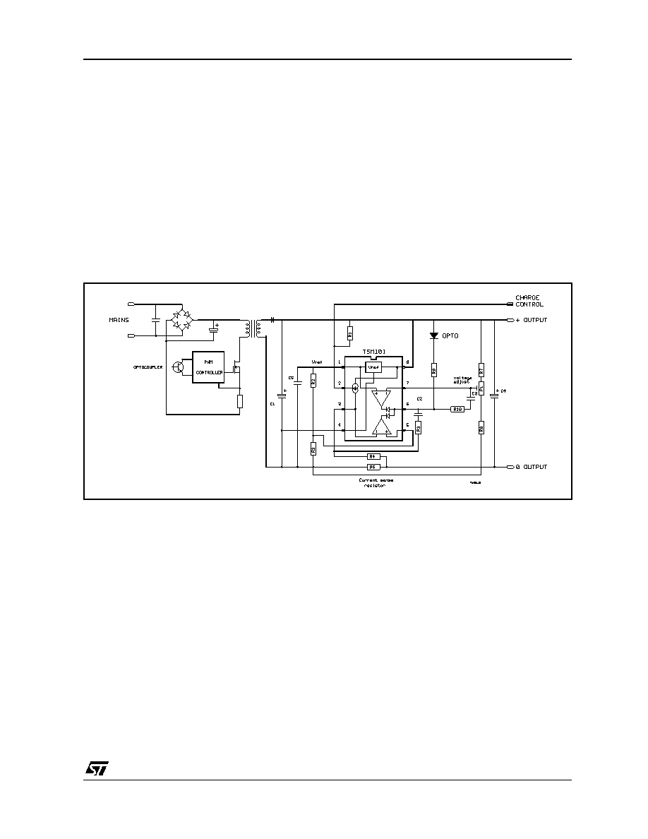
4 - SCHEMATIC DIAGRAM
Figure 2 represents a schematic of the output cir-
cuit of a “classical” SMPS using a TL431 for volt-
age regulation. This circuit is modified to use
theTSM101 and the final circuit is represented in
figure 3.
Figure 3 : SMPS Using the TSM101
5 - IMPROVEMENT
5.1. High frequency compensation
Two R-C devices (R9 + C2 & R10 + C3) are used
to stabilize the regulation at high frequencies.
The calculation of these values is not easy and is
a function of the transfer function of the SMPS.
A guess value for the capacitors C2 and C3 is
100nF.
5.2. Power supply for TSM101
In applications requiring low voltage battery
charge or when the charger is in current regulation
mode, the output voltage can be too low to supply
correctly the TSM101.
The same problem occurs when the output is
short-circuited.
A solution to provide a quasi constant supply volt-
age to the TSM101 is shown at figure 4 : an auxil-
iary winding is added at the secondary side of the
transformer.
This winding is forward coupled to the primary
winding, the voltage across it is directly propor-
tional to the mains rectified voltage, even if the fly-
back voltage is close to zero.
As this auxiliary winding is a voltage source, it is
necessary to add a resistor (R11) on the cathode
of the rectifier (D3) to limit the current.
A low cost regulator (Q2 and Zener diode D4) is
used to power the TSM101. This is necessary with
autoranging SMPS with wide input voltages, for
example 90 to 240V without switching. In standard
SMPS with voltage range from 200 to 240VAC or
100 to 130VAC, this regulator can be removed
and replaced by the small power supply shown on
figure 5 (Raux, Caux, D2).
相关PDF资料 |
PDF描述 |
|---|---|
| TPS3125J18DBVT | 1-CHANNEL POWER SUPPLY SUPPORT CKT, PDSO5 |
| TL4050C41IDBZTQ1 | 2-OUTPUT TWO TERM VOLTAGE REFERENCE, 4.096 V, PDSO3 |
| TS5N214PW | 4-CHANNEL, DIFFERENTIAL MULTIPLEXER, PDSO16 |
| TC7SP3066TU | 1-CHANNEL, SGL POLE SGL THROW SWITCH, PDSO6 |
| TB7101F(T5L1.2,F) | SWITCHING REGULATOR, 1150 kHz SWITCHING FREQ-MAX, PDSO8 |
相关代理商/技术参数 |
参数描述 |
|---|---|
| TSM101IP | 制造商:未知厂家 制造商全称:未知厂家 功能描述:Analog IC |
| TSM101N | 制造商:STMICROELECTRONICS 制造商全称:STMicroelectronics 功能描述:VOLTAGE AND CURRENT CONTROLLER |
| TSM101P | 制造商:STMICROELECTRONICS 制造商全称:STMicroelectronics 功能描述:VOLTAGE AND CURRENT CONTROLLER |
| TSM101电池充电电路 | 制造商:未知厂家 制造商全称:未知厂家 功能描述: |
| TSM102 | 制造商:STMICROELECTRONICS 制造商全称:STMicroelectronics 功能描述:VOLTAGE AND CURRENT CONTROLLER |
发布紧急采购,3分钟左右您将得到回复。