- 您现在的位置:买卖IC网 > PDF目录275093 > UCE-12/10-D48PBL2-Y (MURATA POWER SOLUTIONS INC) 1-OUTPUT 120 W DC-DC REG PWR SUPPLY MODULE PDF资料下载
参数资料
| 型号: | UCE-12/10-D48PBL2-Y |
| 厂商: | MURATA POWER SOLUTIONS INC |
| 元件分类: | 电源模块 |
| 英文描述: | 1-OUTPUT 120 W DC-DC REG PWR SUPPLY MODULE |
| 封装: | MODULE-8 |
| 文件页数: | 15/16页 |
| 文件大小: | 291K |
| 代理商: | UCE-12/10-D48PBL2-Y |
UCE Series
Isolated, High-Density, Eighth-Brick
Low Prole DC/DC Converters
www.murata-ps.com
email: sales@murata-ps.com
Input Fusing
Certain applications and/or safety agencies may require fuses at the inputs of
power conversion components. Fuses should also be used when there is the
possibility of sustained input voltage reversal which is not current-limited. For
greatest safety, we recommend a fast blow fuse installed in the ungrounded
input supply line with a value which is approximately twice the maximum line
current, calculated at the lowest input voltage.
The installer must observe all relevant safety standards and regulations. For
safety agency approvals, install the converter in compliance with the end-user
safety standard.
Input Reverse-Polarity Protection
If the input voltage polarity is reversed, an internal body diode will become
forward biased and likely draw excessive current from the power source. If this
source is not current-limited or the circuit appropriately fused, it could cause
permanent damage to the converter. Please be sure to install a properly-
rated external input fuse.
Input Under-Voltage Shutdown and Start-Up Threshold
Under normal start-up conditions, converters will not begin to regulate properly
until the rising input voltage exceeds and remains at the Start-Up Threshold
Voltage (see Specications). Once operating, converters will not turn off until
the input voltage drops below the Under-Voltage Shutdown Limit. Subsequent
restart will not occur until the input voltage rises again above the Start-Up
Threshold. This built-in hysteresis prevents any unstable on/off operation at a
single input voltage.
Users should be aware however of input sources near the Under-Voltage
Shutdown whose voltage decays as input current is consumed (such as
capacitor inputs), the converter shuts off and then restarts as the external
capacitor recharges. Such situations could oscillate. To prevent this, make
sure the operating input voltage is well above the UV Shutdown voltage AT ALL
TIMES.
Start-Up Delay
Assuming that the output current is set at the rated maximum, the Vin to Vout
Start-Up Time (see Specications) is the time interval between the point when
the rising input voltage crosses the Start-Up Threshold and the fully loaded
regulated output voltage enters and remains within its specied regulation
band. Actual measured times will vary with input source impedance, external
input capacitance, input voltage slew rate and nal value of the input voltage
as it appears at the converter.
These converters include a soft start circuit to moderate the duty cycle of the
PWM controller at power up, thereby limiting the input inrush current.
The On/Off Remote Control interval from inception to Vout regulated
assumes that the converter already has its input voltage stabilized above the
Start-Up Threshold before the On command. The interval is measured from the
On command until the output enters and remains within its specied regulation
band. The specication assumes that the output is fully loaded at maximum
rated current.
APPLICATION NOTES
Input Source Impedance
These converters will operate to specications without external components,
assuming that the source voltage has very low impedance and reasonable
input voltage regulation. Since real-world voltage sources have nite imped-
ance, performance is improved by adding external lter components. Some-
times only a small ceramic capacitor is sufcient. Since it is difcult to totally
characterize all applications, some experimentation may be needed. Note that
external input capacitors must accept high speed switching currents.
Because of the switching nature of DC/DC converters, the input of these
converters must be driven from a source with both low AC impedance and
adequate DC input regulation. Performance will degrade with increasing input
inductance. Excessive input inductance may inhibit operation. The DC input
regulation species that the input voltage, once operating, must never degrade
below the Shut-Down Threshold under all load conditions. Be sure to use
adequate trace sizes and mount components close to the converter.
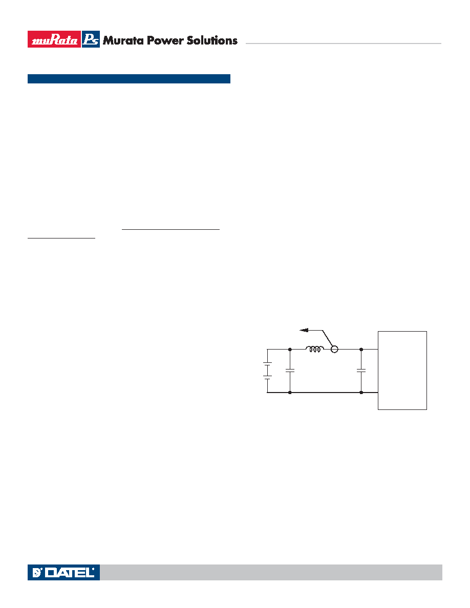
I/O Filtering, Input Ripple Current and Output Noise
All models in this converter series are tested and specied for input reected
ripple current and output noise using designated external input/output compo-
nents, circuits and layout as shown in the gures below. External input capaci-
tors (Cin in the gure) serve primarily as energy storage elements, minimizing
line voltage variations caused by transient IR drops in the input conductors.
Users should select input capacitors for bulk capacitance (at appropriate
frequencies), low ESR and high RMS ripple current ratings. In the gure below,
the Cbus and Lbus components simulate a typical DC voltage bus. Your specic
system conguration may require additional considerations. Please note that
the values of Cin, Lbus and Cbus will vary according to the specic converter
model.
In critical applications, output ripple and noise (also referred to as periodic
and random deviations or PARD) may be reduced by adding lter elements
such as multiple external capacitors. Be sure to calculate component tempera-
ture rise from reected AC current dissipated inside capacitor ESR.
In gure 3, the two copper strips simulate real-world printed circuit imped-
ances between the power supply and its load. In order to minimize circuit
errors and standardize tests between units, scope measurements should be
made using BNC connectors or the probe ground should not exceed one half
inch and soldered directly to the xture.
Figure 2. Measuring Input Ripple Current
CIN
VIN
CBUS
LBUS
CIN = 33μF, ESR < 700mΩ @ 100kHz
CBUS = 220μF, ESR < 100mΩ @ 100kHz
LBUS = 12μH
4
1
+INPUT
INPUT
CURRENT
PROBE
TO
OSCILLOSCOPE
+
–
+
–
04 May 2010
MDC_UCE.A27 Page 8 of 16
相关PDF资料 |
PDF描述 |
|---|---|
| UCE-2.5/20-D48PBHL1-C | 1-OUTPUT 50 W DC-DC REG PWR SUPPLY MODULE |
| UV28-24-S | 1-OUTPUT DC-DC REG PWR SUPPLY MODULE |
| UC2861DW | 1.5 A SWITCHING CONTROLLER, 1000 kHz SWITCHING FREQ-MAX, PDSO16 |
| UARAM2CF1 | SPECIALTY ANALOG CIRCUIT, DMA7 |
| UARAM2CF3 | SPECIALTY ANALOG CIRCUIT, DMA7 |
相关代理商/技术参数 |
参数描述 |
|---|---|
| UCE13N02D1B | 制造商:JOHNSON ELECTRIC 功能描述:Motor; Linear Stepper; Bipolar; Standard Magnet; 28 X 31 mm Dimensions 制造商:Ledex 功能描述:STEPPER LINEAR MOTOR; Coil Type:Bipolar; Torque Max:35in-oz; No. of Phases:Two; Resistance:24ohm; Coil Type:Bipolar; Shaft Configuration:Bipolar; Step Resolution:7.5; Voltage Rating:24VDC |
| UCE13N02D1R | 制造商:Ledex 功能描述:STEPPER LINEAR MOTOR; Coil Type:Bipolar; Torque Max:35in-oz; No. of Phases:Two; Coil Type:Bipolar; Shaft Configuration:Bipolar; Step Resolution:7.5; Voltage Rating:24VDC |
| UCE-2.5/20-D48NB-C | 功能描述:DC/DC转换器 48V 2.5VoUt 20A 50W neg polrty w/Baseplt RoHS:否 制造商:Murata 产品: 输出功率: 输入电压范围:3.6 V to 5.5 V 输入电压(标称): 输出端数量:1 输出电压(通道 1):3.3 V 输出电流(通道 1):600 mA 输出电压(通道 2): 输出电流(通道 2): 安装风格:SMD/SMT 封装 / 箱体尺寸: |
| UCE-2.5/20-D48N-C | 功能描述:DC/DC转换器 48V 2.5Vout 20A 50W negative polarity RoHS:否 制造商:Murata 产品: 输出功率: 输入电压范围:3.6 V to 5.5 V 输入电压(标称): 输出端数量:1 输出电压(通道 1):3.3 V 输出电流(通道 1):600 mA 输出电压(通道 2): 输出电流(通道 2): 安装风格:SMD/SMT 封装 / 箱体尺寸: |
| UCE-2.5/20-D48NL1-C | 制造商:Murata Power Solutions 功能描述:- Trays |
发布紧急采购,3分钟左右您将得到回复。