- 您现在的位置:买卖IC网 > PDF目录19538 > UEE-3.3/30-D48NM-C (Murata Power Solutions Inc)CONV DC/DC 48VIN 3.3VOUT 99W SMD PDF资料下载
参数资料
| 型号: | UEE-3.3/30-D48NM-C |
| 厂商: | Murata Power Solutions Inc |
| 文件页数: | 26/29页 |
| 文件大小: | 0K |
| 描述: | CONV DC/DC 48VIN 3.3VOUT 99W SMD |
| 产品培训模块: | UEE Series |
| 标准包装: | 1 |
| 系列: | UEE |
| 类型: | 隔离 |
| 输出数: | 1 |
| 电压 - 输入(最小): | 36V |
| 电压 - 输入(最大): | 75V |
| Voltage - Output 1: | 3.3V |
| 电流 - 输出(最大): | 30A |
| 电源(瓦) - 制造商系列: | 99W |
| 电压 - 隔离: | 2.25kV(2250V) |
| 特点: | 具有远程开/关功能 |
| 安装类型: | 表面贴装 |
| 封装/外壳: | 8-DIP SMD 模块,1/8 砖 |
| 尺寸/尺寸: | 2.30" L x 0.90" W x 0.40" H(58.4mm x 22.9mm x 10.2mm) |
| 包装: | 标准包装 |
| 工作温度: | -40°C ~ 85°C |
| 效率: | 90% |
| 电源(瓦特)- 最大: | 99W |
| 其它名称: | 811-2282-6 |
第1页第2页第3页第4页第5页第6页第7页第8页第9页第10页第11页第12页第13页第14页第15页第16页第17页第18页第19页第20页第21页第22页第23页第24页第25页当前第26页第27页第28页第29页
�� �
�
�UEE� Series�
�Isolated,� High-Density,� Eighth-Brick�
�DOSA� Low� Pro?le� DC-DC� Converters�
�Note� that� the� temperatures� are� of� the� ambient� air?ow,� not� the� converter�
�itself� which� is� obviously� running� at� higher� temperature� than� the� outside� air.�
�Also� note� that� very� low� ?ow� rates� (below� about� 25� LFM)� are� similar� to� “natural�
�convection,”� that� is,� not� using� fan-forced� air?ow.�
�Murata� Power� Solutions� makes� Characterization� measurements� in� a� closed�
�cycle� wind� tunnel� with� calibrated� air?ow.� We� use� both� thermocouples� and� an�
�infrared� camera� system� to� observe� thermal� performance.� As� a� practical� matter,�
�it� is� quite� dif?cult� to� insert� an� anemometer� to� precisely� measure� air?ow� in�
�most� applications.� Sometimes� it� is� possible� to� estimate� the� effective� air?ow� if�
�you� thoroughly� understand� the� enclosure� geometry,� entry/exit� ori?ce� areas� and�
�the� fan� ?owrate� speci?cations.�
�CAUTION:� If� you� exceed� these� Derating� guidelines,� the� converter� may� have�
�an� unplanned� Over� Temperature� shut� down.� Also,� these� graphs� are� all� collected�
�near� Sea� Level� altitude.� Be� sure� to� reduce� the� derating� for� higher� altitude.�
�Output� Overvoltage� Protection� (OVP)�
�This� converter� monitors� its� output� voltage� for� an� over-voltage� condition.� If�
�the� output� exceeds� OVP� limits,� the� sensing� circuit� will� power� down� the� unit,�
�and� the� output� voltage� will� decrease.� After� a� time-out� period,� the� PWM� will�
�automatically� attempt� to� restart,� causing� the� output� voltage� to� ramp� up� to� its�
�rated� value.� It� is� not� necessary� to� power� down� and� reset� the� converter� for� the�
�automatic� OVP-recovery� restart.�
�If� the� fault� condition� persists� and� the� output� voltage� climbs� to� excessive�
�levels,� the� OVP� circuitry� will� initiate� another� shutdown� cycle.� This� on/off� cycling�
�is� referred� to� as� “hiccup”� mode.�
�Output� Fusing�
�The� converter� is� extensively� protected� against� current,� voltage� and� temperature�
�extremes.� However� your� application� circuit� may� need� additional� protection.� In�
�the� extremely� unlikely� event� of� output� circuit� failure,� excessive� voltage� could� be�
�applied� to� your� circuit.� Consider� using� appropriate� external� protection.�
�Output� Current� Limiting�
�As� soon� as� the� output� current� increases� to� approximately� 125%� to� 150%� of�
�its� maximum� rated� value,� the� DC-DC� converter� will� enter� a� current-limiting�
�mode.� The� output� voltage� will� decrease� proportionally� with� increases� in� output�
�current,� thereby� maintaining� a� somewhat� constant� power� output.� This� is� also�
�commonly� referred� to� as� power� limiting.�
�Current� limiting� inception� is� de?ned� as� the� point� at� which� full� power� falls�
�rapid� on/off� cycling� is� called� “hiccup� mode.”� The� hiccup� cycling� reduces� the�
�average� output� current,� thereby� preventing� excessive� internal� temperatures�
�and/or� component� damage.�
�The� “hiccup”� system� differs� from� older� latching� short� circuit� systems�
�because� you� do� not� have� to� power� down� the� converter� to� make� it� restart.� The�
�system� will� automatically� restore� operation� as� soon� as� the� short� circuit� condi-�
�tion� is� removed.�
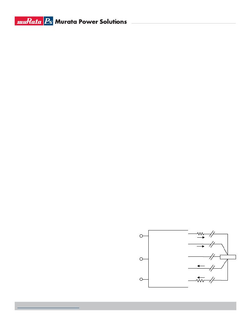
�Remote� Sense� Input� (Models� UEE-3.3/30-D48� only)�
�Use� the� Sense� inputs� with� caution.� Sense� is� normally� connected� at� the� load� .�
�Sense� inputs� compensate� for� output� voltage� inaccuracy� delivered� at� the� load.�
�This� is� done� by� correcting� IR� voltage� drops� along� the� output� wiring� and� the�
�current� carrying� capacity� of� PC� board� etch.� This� output� drop� (the� difference�
�between� Sense� and� Vout� when� measured� at� the� converter)� should� not� exceed�
�0.5V.� Consider� using� heavier� wire� if� this� drop� is� excessive.� Sense� inputs� also�
�improve� the� stability� of� the� converter� and� load� system� by� optimizing� the� control�
�loop� phase� margin.�
�Note:� The� Sense� input� and� power� Vout� lines� are� internally� connected� through�
�low� value� resistors� to� their� respective� polarities� so� that� the� converter� can�
�operate� without� external� connection� to� the� Sense.� Nevertheless,� if� the� Sense�
�function� is� not� used� for� remote� regulation,� the� user� should� connect� +Sense� to�
�+Vout� and� –Sense� to� –Vout� at� the� converter� pins.�
�The� remote� Sense� lines� carry� very� little� current.� They� are� also� capacitively�
�coupled� to� the� output� lines� and� therefore� are� in� the� feedback� control� loop� to�
�regulate� and� stabilize� the� output.� As� such,� they� are� not� low� impedance� inputs�
�and� must� be� treated� with� care� in� PC� board� layouts.� Sense� lines� on� the� PCB�
�should� run� adjacent� to� DC� signals,� preferably� Ground.� In� cables� and� discrete�
�wiring,� use� twisted� pair,� shielded� tubing� or� similar� techniques.�
�Any� long,� distributed� wiring� and/or� signi?cant� inductance� introduced� into� the�
�Sense� control� loop� can� adversely� affect� overall� system� stability.� If� in� doubt,� test�
�your� applications� by� observing� the� converter’s� output� transient� response� during�
�step� loads.� There� should� not� be� any� appreciable� ringing� or� oscillation.� You�
�may� also� adjust� the� output� trim� slightly� to� compensate� for� voltage� loss� in� any�
�external� ?lter� elements.� Do� not� exceed� maximum� power� ratings.�
�Contact� and� PCB� resistance�
�losses� due� to� IR� drops�
�below� the� rated� tolerance.� See� the� Performance/Functional� Speci?cations.�
�Note� particularly� that� the� output� current� may� brie?y� rise� above� its� rated� value�
�in� normal� operation� as� long� as� the� average� output� power� is� not� exceeded.� This�
�enhances� reliability� and� continued� operation� of� your� application.� If� the� output�
�+� VIN�
�+VOUT�
�+SENSE�
�I� OUT�
�Sense� Current�
�current� is� too� high,� the� converter� will� enter� the� short� circuit� condition.�
�Output� Short� Circuit� Condition�
�When� a� converter� is� in� current-limit� mode,� the� output� voltage� will� drop� as� the�
�output� current� demand� increases.� If� the� output� voltage� drops� too� low� (approxi-�
�mately� 98%� of� nominal� output� voltage� for� most� models),� the� magnetically�
�coupled� voltage� used� to� develop� the� PWM� bias� voltage� will� also� drop,� thereby�
�ON/OFF�
�CONTROL�
�–� VIN�
�TRIM�
�?� SENSE�
�-VOUT�
�Sense� Return�
�I� OUT� Return�
�LOAD�
�shutting� down� the� PWM� controller.� Following� a� time-out� period,� the� PWM� will�
�restart,� causing� the� output� voltage� to� begin� rising� to� its� appropriate� value.�
�If� the� short-circuit� condition� persists,� another� shutdown� cycle� will� initiate.� This�
�Contact� and� PCB� resistance�
�losses� due� to� IR� drops�
�Figure� 9.� Remote� Sense� Circuit� Con?guration�
�www.murata-ps.com/support�
�MDC_UEE_Series.C01� Page� 26� of� 29�
�相关PDF资料 |
PDF描述 |
|---|---|
| TMK212SD472KD-T | CAP CER 4700PF 25V 10% 0805 |
| VE-24R-CY-F4 | CONVERTER MOD DC/DC 7.5V 50W |
| RSA30DTBD-S664 | CONN EDGECARD 60POS R/A .125 SLD |
| EPM570GT144C3N | IC MAX II CPLD 570 LE 144-TQFP |
| RS3D-13-F | DIODE FAST REC 200V 3A SMC |
相关代理商/技术参数 |
参数描述 |
|---|---|
| UEE-5/30-D48NB-C | 功能描述:DC/DC CONVERTER 5V 150W 制造商:murata power solutions inc. 系列:UEE 150W 包装:托盘 零件状态:有效 类型:隔离模块 输出数:1 电压 - 输入(最小值):36V 电压 - 输入(最大值):75V 电压 - 输出 1:5V 电压 - 输出 2:- 电压 - 输出 3:- 电流 - 输出(最大值):30A 功率(W) - 制造系列:150W 电压 - 隔离:2.25kV(2250V) 应用:ITE(商业) 特性:远程开/关,OCP,OTP,SCP,UVLO 安装类型:通孔 封装/外壳:8-DIP 模块,1/8 砖 大小/尺寸:2.30" 长 x 0.90" 宽 x 0.50" 高(58.4mm x 22.9mm x 12.7mm) 工作温度:-40°C ~ 85°C 效率:92% 功率(W) - 最大值:150W 标准包装:21 |
| UEF-AUTOESL-25 | 制造商:Xilinx 功能描述:UNIVERSITY AUTOESL, 25 LICENSE BUNDLE - Virtual or Non-Physical Inventory (Software & Literature) 制造商:Xilinx 功能描述:AUTOESL 25 LICENSE BUNDLE |
| UEF-AUTOESL-50 | 制造商:Xilinx 功能描述:AUTOESL 50 LICENSE BUNDLE |
| UEF-ISE-DSP-25 | 制造商:Xilinx 功能描述:ISE DESIGN SUITE DSP 25 LICENSE |
| UEF-ISE-DSP-50 | 制造商:Xilinx 功能描述:ISE DESIGN SUITE DSP 50 LICENSE |
发布紧急采购,3分钟左右您将得到回复。