- 您现在的位置:买卖IC网 > PDF目录20868 > UEI15-050-Q48N-C (Murata Power Solutions Inc)CONV DC/DC 15W 5V 3A PDF资料下载
参数资料
| 型号: | UEI15-050-Q48N-C |
| 厂商: | Murata Power Solutions Inc |
| 文件页数: | 4/17页 |
| 文件大小: | 0K |
| 描述: | CONV DC/DC 15W 5V 3A |
| 产品培训模块: | Medium Power Industrial DC/DC Converters 5 ~ 60W UEI Series DC-DC Converter |
| 标准包装: | 90 |
| 系列: | UEI15 |
| 类型: | 隔离 |
| 输出数: | 1 |
| 电压 - 输入(最小): | 18V |
| 电压 - 输入(最大): | 75V |
| Voltage - Output 1: | 5V |
| 电流 - 输出(最大): | 3A |
| 电源(瓦) - 制造商系列: | 15W |
| 电压 - 隔离: | 2.25kV(2250V) |
| 安装类型: | 通孔 |
| 封装/外壳: | 6-DIP 模块 |
| 尺寸/尺寸: | 1.10" L x 0.96" W x 0.32" H(27.9mm x 24.4mm x 8.1mm) |
| 包装: | 管件 |
| 工作温度: | -40°C ~ 85°C |
| 效率: | 86% |
| 电源(瓦特)- 最大: | 15W |
| 产品目录页面: | 2721 (CN2011-ZH PDF) |
| 其它名称: | 811-1867-5 |
�� �
�
�UEI15� Series�
�Isolated� Wide� Input� Range� 15-Watt� DC/DC� Converters�
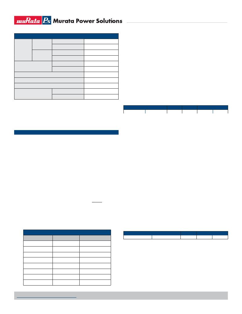
�Input�
�Volts� Max.� continuous�
�ABSOLUTE MAXIMUM RATINGS�
�Volts� Max.� continuous�
�Q12� models�
�Volts,� transient� 100mS�
�Voltage�
�Q48� models�
�Volts,� transient� 100mS�
�36� VDC�
�50� VDC�
�75� VDC�
�100� VDC�
�(4)� Mean� Time� Before� Failure� is� calculated� using� the� Telcordia� (Belcore)� SR-�
�332� Method� 1,� Case� 3,� ground� ?xed� conditions,� Tpcboard=+25� deg.C,� full� load,�
�natural� air� convection.�
�(5)� The� On/Off� Control� is� normally� controlled� by� a� switch.� But� it� may� also� be�
�driven� with� external� logic� or� by� applying� appropriate� external� voltages� which� are�
�referenced� to� Input� Common.� The� On/Off� Control� Input� should� use� either� an� open�
�On/Off� control,�
�referred� to� –V� IN�
�Volts,� Min.�
�Volts,� Max.�
�–0.3�
�15�
�collector� or� open� drain� transistor.�
�(6)� Output� current� limiting� begins� when� the� output� voltage� degrades�
�Input� Reverse� Polarity� Protection�
�Output� Overvoltage,� Volts� Max.�
�Output� Current,� sustained� short� circuit�
�Range,� Min.� oC�
�Storage� Temperature�
�Max.� oC�
�See� fuse� section�
�V� OUT� nom.� +20%�
�Current-limited,� see� specs�
�-55�
�+125�
�approximately� 2%� from� the� selected� setting.�
�(7)� The� outputs� are� not� intended� to� sink� appreciable� reverse� current.� This� may�
�damage� the� outputs.�
�(8)� Output� noise� may� be� further� reduced� by� adding� an� external� ?lter.� See� I/O� Fil-�
�tering� and� Noise� Reduction.�
�(9)� All� models� are� fully� operational� and� meet� published� speci?cations,� including�
�“cold� start”� at� –40°C.�
�Absolute� Maximum� Ratings�
�Absolute� maximums� are� stress� ratings.� Exposure� of� devices� to� greater� than� any�
�Root� Models�
�All� UEI15� Q12�
�Conditions�
�Start� up� at� –40°C�
�Minimum�
�10�
�Typical�
�10.5�
�Maximum�
�11�
�Units�
�Vdc�
�of� these� conditions� may� adversely� affect� long-term� reliability.� Proper� operation�
�under� conditions� other� than� those� listed� in� the� Performance/Functional� Speci?-�
�cations� is� neither� implied� nor� recommended.�
�SPECIFICATION� NOTES�
�(1)� All� models� are� tested� and� speci?ed� with� external� capacitors� listed� in� the�
�table� below.� The� external� capacitors� listed� below� are� ONLY� for� establishing� test�
�speci?cations.� They� are� required� for� our� test� ?xtures� and� equipment.� Your� applica-�
�tion� may� not� need� them.� The� converter� is� stable� with� no� external� capacitors� but�
�Murata� Power� Solutions� strongly� recommends� external� caps.� All� caps� are� low-ESR�
�types.� Where� two� or� more� capacitors� are� listed,� these� are� connected� in� parallel.� All�
�caps� should� mount� close� to� the� DC/DC� using� short� leads.�
�All� speci?cations� are� typical� unless� noted.� General� conditions� for� Speci?ca-�
�tions� are� +25� deg.C,� V� IN� =nominal,� V� OUT� =nominal,� full� load.� Adequate� air?ow� must�
�be� supplied� for� extended� testing� under� power.�
�(2)� Input� Ripple� Current� is� tested� and� speci?ed� over� a� 5� Hz� to� 20� MHz� band-�
�width.� Input� ?ltering� is� C� IN� =33� μF,� 100V� tantalum,� C� BUS� =220� μF,� 100V� electro-�
�lytic,� L� BUS� =12� μH.�
�(3)� Note� that� Maximum� Power� Derating� curves� indicate� an� average� current� at�
�nominal� input� voltage.� At� higher� temperatures� and/or� lower� air?ow,� the� DC/DC�
�converter� will� tolerate� brief� full� current� outputs� if� the� total� RMS� current� over� time�
�does� not� exceed� the� Derating� curve.� All� Derating� curves� are� presented� at� sea� level�
�altitude.� Be� aware� of� reduced� power� dissipation� with� increasing� density� altitude.�
�(10)� Regulation� speci?cations� describe� the� deviation� as� the� line� input� voltage�
�or� output� load� current� is� varied� from� a� nominal� midpoint� value� to� either� extreme.�
�(11)� The� output� overvoltage� protection� is� automatic� recovery� after� fault�
�removal.� The� overvoltage� may� occur� either� from� internal� failure� or� from� an�
�external� forcing� voltage� as� in� a� shared� power� system.�
�(12)� Output� current� limit� and� short� circuit� protection� is� non-latching.� When� the�
�overcurrent� fault� is� removed,� the� converter� will� immediately� recover.�
�(13)� Do� not� exceed� maximum� power� speci?cations� when� adjusting� the� output�
�trim.�
�(14)� At� zero� output� current,� the� output� may� contain� low� frequency� components�
�which� exceed� the� ripple� speci?cation.� The� output� may� be� operated� inde?nitely�
�with� no� load.�
�(15)� If� reverse� polarity� is� accidentally� applied� to� the� input,� to� ensure� reverse� in-�
�put� protection� with� full� output� load,� always� connect� an� external� input� fuse� in� series�
�with� the� +V� IN� input.� Use� approximately� twice� the� full� load� input� current� rating� at�
�minimum� input� voltage.�
�(16)� “Hiccup”� operation� repeatedly� attempts� to� restart� the� converter� with� a�
�brief,� full-current� output.� If� the� overcurrent� condition� still� exists,� the� restart� current�
�will� be� removed� and� then� tried� again.� This� short� current� pulse� prevents� over-�
�heating� and� damaging� the� converter.� Once� the� fault� is� removed,� the� converter�
�immediately� recovers� normal� operation.�
�(17)� On� model� UEI15-050-Q48,� if� V� IN� <20V,� output� trim� may� only� be� adjusted�
�downwards� from� +5.0V� (more� negative).�
�(18)� Typical� values� s� hown. For minimum and maximum values see table below.�
�INPUT/OUTPUT� EXTERNAL� TEST� CAPACITORS�
�Root� Models�
�Conditions�
�Minimum�
�Maximum�
�Units�
�Model�
�Input� Capacitor�
�Output� Capacitor(s)�
�All� UEI15� Q12�
�@+25°C�
�8.8�
�10�
�Vdc�
�UEI15-033-Q12�
�UEI15-033-Q48�
�UEI15-050-Q12�
�UEI15-050-Q48�
�UEI15-120-Q12�
�UEI15-120-Q48�
�UEI15-150-Q12�
�UEI15-150-Q48�
�100� μF�
�4.7� μF� ceramic�
�100� μF�
�4.7� μF� ceramic�
�100� μF�
�4.7� μF� ceramic�
�100� μF�
�4.7� μF� ceramic�
�1� μF� &� 10� μF�
�1� μF� &� 10� μF�
�1� μF� &� 10� μF�
�1� μF� &� 10� μF�
�1� μF� &� 10� μF�
�1� μF� &� 10� μF�
�1� μF� &� 10� μF�
�1� μF� &� 10� μF�
�CAUTION:� This� product� is� not� internally� fused.� To� comply� with� safety�
�agency� certi?cations� and� to� avoid� injury� to� personnel� or� equipment,� the� user�
�must� connect� an� external� fast-blow� fuse� to� the� input� terminals.� See� fuse�
�information.�
�(19)� All� models� require� 10%� of� Imax� minimum� output� load� to� meet� speci?-�
�cations.� However,� they� will� not� be� damaged� at� zero� output� load.�
�www.murata-ps.com/support�
�MDC_UEI15W.C14� Page� 4� of� 17�
�相关PDF资料 |
PDF描述 |
|---|---|
| P51-500-A-O-M12-4.5OVP-000-000 | SENSOR 500PSI 7/16-20UNF 2B 4.5V |
| REC3-2412SRWZ/H6/C/SMD-R | CONV DC/DC 3W 9-36VIN 12VOUT |
| UEI15-033-Q48N-C | CONV DC/DC 16.5W 3.3V 5A |
| P51-200-S-A-I12-4.5V-000-000 | SENSOR 200PSI 1/4-18NPT .5-4.5V |
| P51-300-A-O-M12-4.5OVP-000-000 | SENSOR 300PSI 7/16-20UNF 2B 4.5V |
相关代理商/技术参数 |
参数描述 |
|---|---|
| UEI15-050-Q48NM-C | 功能描述:DC/DC转换器 15W 48Vin 5Vout 3A Neg Polarity SMT RoHS:否 制造商:Murata 产品: 输出功率: 输入电压范围:3.6 V to 5.5 V 输入电压(标称): 输出端数量:1 输出电压(通道 1):3.3 V 输出电流(通道 1):600 mA 输出电压(通道 2): 输出电流(通道 2): 安装风格:SMD/SMT 封装 / 箱体尺寸: |
| UEI15-050-Q48P-C | 功能描述:DC/DC转换器 48Vin 5Vout 3A 15W Pos polarity RoHS:否 制造商:Murata 产品: 输出功率: 输入电压范围:3.6 V to 5.5 V 输入电压(标称): 输出端数量:1 输出电压(通道 1):3.3 V 输出电流(通道 1):600 mA 输出电压(通道 2): 输出电流(通道 2): 安装风格:SMD/SMT 封装 / 箱体尺寸: |
| UEI15-050-Q48PM-C | 功能描述:DC/DC转换器 15W 48Vin 5Vout 3A Pos Polarity SMT RoHS:否 制造商:Murata 产品: 输出功率: 输入电压范围:3.6 V to 5.5 V 输入电压(标称): 输出端数量:1 输出电压(通道 1):3.3 V 输出电流(通道 1):600 mA 输出电压(通道 2): 输出电流(通道 2): 安装风格:SMD/SMT 封装 / 箱体尺寸: |
| UEI15-120-Q12 | 制造商:MURATA 制造商全称:Murata Manufacturing Co., Ltd. 功能描述:Isolated Wide Input Range 15-Watt DC/DC Converters |
| UEI15-120-Q12N-C | 功能描述:DC/DC转换器 24Vin 12Vout 1.3A 15.6W Neg polarity RoHS:否 制造商:Murata 产品: 输出功率: 输入电压范围:3.6 V to 5.5 V 输入电压(标称): 输出端数量:1 输出电压(通道 1):3.3 V 输出电流(通道 1):600 mA 输出电压(通道 2): 输出电流(通道 2): 安装风格:SMD/SMT 封装 / 箱体尺寸: |
发布紧急采购,3分钟左右您将得到回复。