- 您现在的位置:买卖IC网 > PDF目录20869 > UEI25-050-D48N-C (Murata Power Solutions Inc)CONV DC/DC 25W 5V PDF资料下载
参数资料
| 型号: | UEI25-050-D48N-C |
| 厂商: | Murata Power Solutions Inc |
| 文件页数: | 20/24页 |
| 文件大小: | 0K |
| 描述: | CONV DC/DC 25W 5V |
| 产品培训模块: | UEI25 Series |
| 产品目录绘图: | UEI25 Series |
| 标准包装: | 90 |
| 系列: | UEI25 |
| 类型: | 隔离 |
| 输出数: | 1 |
| 电压 - 输入(最小): | 36V |
| 电压 - 输入(最大): | 75V |
| Voltage - Output 1: | 5V |
| 电流 - 输出(最大): | 5A |
| 电源(瓦) - 制造商系列: | 25W |
| 电压 - 隔离: | 2.25kV(2250V) |
| 特点: | 具有远程开/关功能 |
| 安装类型: | 通孔 |
| 封装/外壳: | 6-DIP 模块 |
| 尺寸/尺寸: | 1.10" L x 0.96" W x 0.32" H(27.9mm x 24.4mm x 8.1mm) |
| 包装: | 管件 |
| 工作温度: | -40°C ~ 85°C |
| 效率: | 89% |
| 电源(瓦特)- 最大: | 25W |
| 产品目录页面: | 2719 (CN2011-ZH PDF) |
| 其它名称: | 811-2223 |
�� �
�
�UEI25� Series�
�Single� Output� Isolated� 25-Watt� DC/DC� Converters�
�CAUTION:� If� you� exceed� these� Derating� guidelines,� the� converter� may� have�
�an� unplanned� Over� Temperature� shut� down.� Also,� these� graphs� are� all� collected�
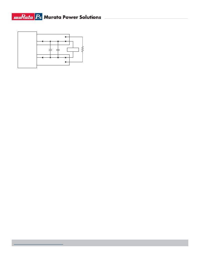
�+VOUT�
�near� Sea� Level� altitude.� Be� sure� to� reduce� the� derating� for� higher� altitude.�
�Output� Overvoltage� Protection� (OVP)�
�C1�
�C2�
�SCOPE�
�R� LOAD�
�This� converter� monitors� its� output� voltage� for� an� over-voltage� condition� using�
�an� on-board� electronic� comparator.� The� signal� is� optically� coupled� to� the� pri-�
�?VOUT�
�C1� =� 1μF�
�C2� =� 10μF�
�LOAD� 2-3� INCHES� (51-76mm)� FROM� MODULE�
�Figure� 3.� Measuring� Output� Ripple� and� Noise� (PARD)�
�Minimum� Output� Loading� Requirements�
�These� converters� employ� a� synchronous� recti?er� design� topology.� All� models�
�regulate� within� speci?cation� and� are� stable� from� 0%� load� to� full� load� conditions,�
�unless� otherwise� speci?ed.� Operation� under� no� load� will� not� damage� the� con-�
�verter� but� might,� however,� slightly� increase� regulation,� output� ripple,� and� noise.�
�Thermal� Shutdown�
�To� protect� against� thermal� over-stress,� these� converters� include� thermal� shut-�
�down� circuitry.� If� environmental� conditions� cause� the� temperature� of� the� DC/�
�DC’s� to� rise� above� the� Operating� Temperature� Range� up� to� the� shutdown� tem-�
�perature,� an� on-board� electronic� temperature� sensor� will� power� down� the� unit.�
�When� the� temperature� decreases� below� the� turn-on� threshold,� the� converter�
�will� automatically� restart.� There� is� a� small� amount� of� hysteresis� to� prevent�
�rapid� on/off� cycling.� CAUTION:� If� you� operate� too� close� to� the� thermal� limits,� the�
�converter� may� shut� down� suddenly� without� warning.� Be� sure� to� thoroughly� test�
�your� application� to� avoid� unplanned� thermal� shutdown.�
�Temperature� Derating� Curves�
�The� graphs� in� the� performance� data� section� illustrate� typical� operation� under� a�
�variety� of� conditions.� The� Derating� curves� show� the� maximum� continuous� ambient�
�air� temperature� and� decreasing� maximum� output� current� which� is� acceptable� under�
�increasing� forced� air?ow� measured� in� Linear� Feet� per� Minute� (“LFM”).� Note� that�
�these� are� AVERAGE� measurements.� The� converter� will� accept� brief� increases� in� tem-�
�perature� and/or� current� or� reduced� air?ow� as� long� as� the� average� is� not� exceeded.�
�Note� that� the� temperatures� are� of� the� ambient� air?ow,� not� the� converter� it-�
�self� which� is� obviously� running� at� higher� temperature� than� the� outside� air.� Also�
�note� that� “natural� convection”� is� de?ned� as� very� low� ?ow� rates� which� are� not�
�using� fan-forced� air?ow.� Depending� on� the� application,� “natural� convection”� is�
�usually� about� 30-65� LFM� but� is� not� equal� to� still� air� (0� LFM).�
�Murata� Power� Solutions� makes� Characterization� measurements� in� a� closed�
�cycle� wind� tunnel� with� calibrated� air?ow.� We� use� both� thermocouples� and� an�
�infrared� camera� system� to� observe� thermal� performance.� As� a� practical� matter,�
�it� is� quite� dif?cult� to� insert� an� anemometer� to� precisely� measure� air?ow� in�
�most� applications.� Sometimes� it� is� possible� to� estimate� the� effective� air?ow� if�
�you� thoroughly� understand� the� enclosure� geometry,� entry/exit� ori?ce� areas� and�
�the� fan� ?owrate� speci?cations.�
�mary� side� PWM� controller.� If� the� output� exceeds� OVP� limits,� the� sensing� circuit�
�will� power� down� the� unit,� and� the� output� voltage� will� decrease.� After� a� time-out�
�period,� the� PWM� will� automatically� attempt� to� restart,� causing� the� output� volt-�
�age� to� ramp� up� to� its� rated� value.� It� is� not� necessary� to� power� down� and� reset�
�the� converter� for� this� automatic� OVP-recovery� restart.�
�If� the� fault� condition� persists� and� the� output� voltage� climbs� to� excessive�
�levels,� the� OVP� circuitry� will� initiate� another� shutdown� cycle.� This� on/off� cycling�
�is� referred� to� as� “hiccup”� mode.�
�Output� Fusing�
�The� converter� is� extensively� protected� against� current,� voltage� and� temperature�
�extremes.� However,� your� application� circuit� may� need� additional� protection.� In� the�
�extremely� unlikely� event� of� output� circuit� failure,� excessive� voltage� could� be� applied�
�to� your� circuit.� Consider� using� an� appropriate� external� protection.�
�Output� Current� Limiting�
�As� soon� as� the� output� current� increases� to� approximately� its� overcurrent� limit,�
�the� DC/DC� converter� will� enter� a� current-limiting� mode.� The� output� voltage� will�
�decrease� proportionally� with� increases� in� output� current,� thereby� maintaining� a�
�somewhat� constant� power� output.� This� is� commonly� referred� to� as� power� limiting.�
�Current� limiting� inception� is� de?ned� as� the� point� at� which� full� power� falls�
�below� the� rated� tolerance.� See� the� Performance/Functional� Speci?cations.�
�Note� particularly� that� the� output� current� may� brie?y� rise� above� its� rated� value.�
�This� enhances� reliability� and� continued� operation� of� your� application.� If� the�
�output� current� is� too� high,� the� converter� will� enter� the� short� circuit� condition.�
�Output� Short� Circuit� Condition�
�When a converter is in current-limit mode,the output voltage will drop as�
�the� output� current� demand� increases.� If� the� output� voltage� drops� too� low,� the�
�magnetically� coupled� voltage� used� to� develop� PWM� bias� voltage� will� also� drop,�
�thereby� shutting� down� the� PWM� controller.� Following� a� time-out� period,� the�
�PWM� will� restart,� causing� the� output� voltage� to� begin� rising� to� its� appropriate�
�value.� If� the� short-circuit� condition� persists,� another� shutdown� cycle� will� initi-�
�ate.� This� on/off� cycling� is� called� “hiccup� mode.”� The� hiccup� cycling� reduces� the�
�average� output� current,� thereby� preventing� excessive� internal� temperatures.�
�Trimming� the� Output� Voltage�
�The� Trim� input� to� the� converter� allows� the� user� to� adjust� the� output� voltage� over�
�the� rated� trim� range� (please� refer� to� the� Speci?cations).� In� the� trim� equations�
�and� circuit� diagrams� that� follow,� trim� adjustments� use� a� single� ?xed� resistor�
�connected� between� the� Trim� input� and� either� Vout� pin.� Trimming� resistors� should�
�have� a� low� temperature� coef?cient� (±100� ppm/°C� or� less)� and� be� mounted� close�
�to� the� converter.� Keep� leads� short.� If� the� trim� function� is� not� used,� leave� the� trim�
�unconnected.� With� no� trim,� the� converter� will� exhibit� its� speci?ed� output� voltage�
�accuracy.�
�www.murata-ps.com/support�
�MDC_UEI25W.B09� Page� 20� of� 24�
�相关PDF资料 |
PDF描述 |
|---|---|
| P51-75-A-O-M12-4.5OVP-000-000 | SENSOR 75PSI 7/16-20UNF 2B 4.5V |
| LT3755IUD-1#TRPBF | IC LED DRVR HP CONST CURR 16-QFN |
| G3NA-220B-UTU AC200/240 | RELAY SSR 20A 200-240VAC ZERO |
| LT3755IUD#TRPBF | IC LED DRVR HP CONST CURR 16-QFN |
| LT3517IUF#TRPBF | IC LED DRIVER AUTOMOTIVE 16-QFN |
相关代理商/技术参数 |
参数描述 |
|---|---|
| UEI25-050-D48NM-C | 功能描述:DC/DC转换器 48Vin 5Vout 5A SMT 25W Neg. Polarity RoHS:否 制造商:Murata 产品: 输出功率: 输入电压范围:3.6 V to 5.5 V 输入电压(标称): 输出端数量:1 输出电压(通道 1):3.3 V 输出电流(通道 1):600 mA 输出电压(通道 2): 输出电流(通道 2): 安装风格:SMD/SMT 封装 / 箱体尺寸: |
| UEI25-050-D48P-C | 功能描述:DC/DC转换器 48Vin 5Vout 5A 25W Pos. Polarity RoHS:否 制造商:Murata 产品: 输出功率: 输入电压范围:3.6 V to 5.5 V 输入电压(标称): 输出端数量:1 输出电压(通道 1):3.3 V 输出电流(通道 1):600 mA 输出电压(通道 2): 输出电流(通道 2): 安装风格:SMD/SMT 封装 / 箱体尺寸: |
| UEI25-050-D48PM-C | 功能描述:DC/DC转换器 48Vin 5Vout 5A SMT 25W Pos. Polarity RoHS:否 制造商:Murata 产品: 输出功率: 输入电压范围:3.6 V to 5.5 V 输入电压(标称): 输出端数量:1 输出电压(通道 1):3.3 V 输出电流(通道 1):600 mA 输出电压(通道 2): 输出电流(通道 2): 安装风格:SMD/SMT 封装 / 箱体尺寸: |
| UEI25-120 | 制造商:MURATA 制造商全称:Murata Manufacturing Co., Ltd. 功能描述:Single Output Isolated 25-Watt DC/DC Converters |
| UEI25-120-D48 | 制造商:MURATA 制造商全称:Murata Manufacturing Co., Ltd. 功能描述:Single Output Isolated 25-Watt DC/DC Converters |
发布紧急采购,3分钟左右您将得到回复。