- 您现在的位置:买卖IC网 > PDF目录300050 > ULQ-2/25-D24P (CD TECHNOLOGIES INC) 1-OUTPUT DC-DC REG PWR SUPPLY MODULE PDF资料下载
参数资料
| 型号: | ULQ-2/25-D24P |
| 厂商: | CD TECHNOLOGIES INC |
| 元件分类: | 电源模块 |
| 英文描述: | 1-OUTPUT DC-DC REG PWR SUPPLY MODULE |
| 封装: | 1.450 X 2.300 INCH, 0.350 INCH HEIGHT, QUARTER BRICK PACKAGE-8 |
| 文件页数: | 11/16页 |
| 文件大小: | 566K |
| 代理商: | ULQ-2/25-D24P |
8 - 2 5 A M P , S I N G L E O U T P U T D C / D C C O N V E R T E R S
ULQ Series
Input Fusing
Certain applications and/or safety agencies may require the installation of
fuses at the inputs of power conversion components. Fuses should also be
used if the possibility of sustained, non-current-limited, input-voltage polarity
reversals exists. For DATEL ULQ series DC/DC converters, we recommend
the use of a time delay fuse, installed in the ungrounded input supply line,
with a value no greater than 20 Amps.
As a rule of thumb however, we recommend the use of a normal-blow or
slow-blow fuse with a typical value about twice the maximum input current,
calculated at low line with the converter's minimum efciency.
All relevant national and international safety standards and regulations must
be observed by the installer. For system safety agency approvals, the
converters must be installed in compliance with the requirements of the end-
use safety standard, i.e. IEC/EN/UL60950.
Input Reverse-Polarity Protection
If the input voltage polarity is accidentally reversed, an internal diode will
become forward biased and likely draw excessive current from the power
source. If this source is not current limited or the circuit appropiately fused, it
could cause permanent damage to the converter.
Input Undervoltage Shutdown and Start-Up Threshold
Under normal start-up conditions, devices will not begin to regulate properly
until the ramping-up input voltage exceeds the Start-Up Threshold Voltage.
Once operating, devices will not turn off until the input voltage drops below
the Undervoltage Shutdown limit. Subsequent re-start will not occur until the
input is brought back up to the Start-Up Threshold. This built in hysteresis
prevents any unstable on/off situations from occurring at a single input
voltage.
Start-Up Time
The VIN to VOUT Start-Up Time is the time interval between the point at which
the ramping input voltage crosses the Start-Up Threshold and the fully loaded
output voltage enters and remains within its specied accuracy band. Actual
measured times will vary with input source impedance, external input capaci-
tance, and the slew rate and nal value of the input voltage as it appears at
the converter. The ULQ Series implements a soft start circuit to limit the duty
cycle of its PWM controller at power up, thereby limiting the input inrush current.
The On/Off Control to VOUT start-up time assumes the converter has its
nominal input voltage applied but is turned off via the On/Off Control pin. The
specication denes the interval between the point at which the converter is
turned on (released) and the fully loaded output voltage enters and remains
within its specied accuracy band.
Similar to the VIN to VOUT start-up, the On/Off Control to VOUT start-up
time is also governed by the internal soft start circuitry and external load
capacitance. The difference in start up time from VIN to VOUT and from On/Off
Control to VOUT is therefore insignicant.
Input Overvoltage Shutdown
All 24VIN ULQ DC/DC's are equipped with input overvoltage protection. Input
voltages exceeding the input overvoltage shutdown specication listed in the
Performance/Functional Specications will cause the device to shutdown.
A built-in hysterisis for all models will not allow the converter to restart until
the input voltage is sufciently reduced.
All 48VIN models have the overvoltage shutdown function disabled, based
on requirements to withstand brief input surges and transients to 100V for
up to 100msec without voltage interruption. Contact DATEL to have input
overvoltage shutdown for 48VIN models enabled.
Input Source Impedance
The input of ULQ converters must be driven from a low ac-impedance
source. The DC/DC's performance and stability can be compromised by
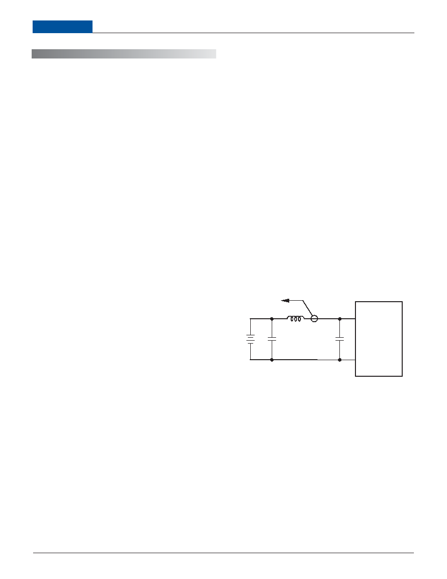
the use of highly inductive source impedances. The input circuit shown in
Figure 2 is a practical solution that can be used to minimize the effects of
inductance in the input traces. For optimum performance, components should
be mounted close to the DC/DC converter.
I/O Filtering, Input Ripple Current, and Output Noise
All models in the ULQ Series are tested/specied for input reected
ripple current and output noise using the specied external input/output
components/circuits and layout as shown in the following two gures. External
input capacitors (CIN in Figure 2) serve primarily as energy-storage elements,
minimizing line voltage variations caused by transient IR drops in conductors
from backplane to the DC/DC. Input caps should be selected for bulk capaci-
tance (at appropriate frequencies), low ESR, and high rms-ripple-current
ratings. The switching nature of DC/DC converters requires that dc voltage
sources have low ac impedance as highly inductive source impedance can
affect system stability. In Figure 2, CBUS and LBUS simulate a typical dc
voltage bus.Your specic system conguration may necessitate additional
considerations.
T E C H N I C A L N O T E S
In critical applications, output ripple/noise (also referred to as periodic and
random deviations or PARD) may be reduced below specied limits using l-
tering techniques, the simplest of which is the installation of additional exter-
nal output capacitors. They function as true lter elements and should be
selected for bulk capacitance, low ESR and appropriate frequency response.
All external capacitors should have appropriate voltage ratings and be
located as close to the converter as possible. Temperature variations for all
relevant parameters should also be taken carefully into consideration. The
most effective combination of external I/O capacitors will be a function of
line voltage and source impedance, as well as particular load and layout
conditions. Our Applications Engineers can recommend potential solutions
and discuss the possibility of our modifying a given device's internal ltering
to meet your specic requirements. Contact our Applications Engineering
Group for additional details.
Figure 2. Measuring Input Ripple Current
CIN
VIN
CBUS
LBUS
CIN = 33F, ESR < 700m
@ 100kHz
CBUS = 220F, ESR < 100m
@ 100kHz
LBUS = 12H
3
1
+INPUT
–INPUT
CURRENT
PROBE
TO
OSCILLOSCOPE
+
–
4
相关PDF资料 |
PDF描述 |
|---|---|
| ULQ-3.3/20-D24NL1 | 1-OUTPUT DC-DC REG PWR SUPPLY MODULE |
| UM-LR-PC | CONNECTOR ACCESSORY |
| UM-PR-PC | CONNECTOR ACCESSORY |
| UM-QA-JJ | CONNECTOR ACCESSORY |
| UM-QLP-1.5-6 | CONNECTOR ACCESSORY |
相关代理商/技术参数 |
参数描述 |
|---|---|
| ULQ2436M | 制造商:ALLEGRO 制造商全称:Allegro MicroSystems 功能描述:COUNTDOWN POWER TIMER |
| ULQ2460A | 制造商:ALLEGRO 制造商全称:Allegro MicroSystems 功能描述:ELECTRONIC IGNITION TIMING |
| ULQ2460C | 制造商:ALLEGRO 制造商全称:Allegro MicroSystems 功能描述:ELECTRONIC IGNITION TIMING |
| ULQ2460LW | 制造商:Allegro MicroSystems LLC 功能描述: |
| ULQ2470L | 制造商:未知厂家 制造商全称:未知厂家 功能描述:BUS DRIVER / RECEIVER |
发布紧急采购,3分钟左右您将得到回复。