- 您现在的位置:买卖IC网 > PDF目录8081 > ULS-12/5-D48PH-C (Murata Power Solutions Inc)CONVERT DC/DC 12V @ 5A POS CC PDF资料下载
参数资料
| 型号: | ULS-12/5-D48PH-C |
| 厂商: | Murata Power Solutions Inc |
| 文件页数: | 21/24页 |
| 文件大小: | 0K |
| 描述: | CONVERT DC/DC 12V @ 5A POS CC |
| 标准包装: | 128 |
| 系列: | ULS |
| 类型: | 隔离 |
| 输出数: | 1 |
| 电压 - 输入(最小): | 36V |
| 电压 - 输入(最大): | 75V |
| Voltage - Output 1: | 12V |
| 电流 - 输出(最大): | 5A |
| 电源(瓦) - 制造商系列: | 60W |
| 电压 - 隔离: | 2.25kV(2250V) |
| 特点: | 具有远程开/关功能 |
| 安装类型: | 通孔 |
| 封装/外壳: | 8-DIP 模块,1/16 砖 |
| 尺寸/尺寸: | 1.30" L x 0.90" W x 0.40" H(33.0mm x 22.9mm x 10.2mm) |
| 包装: | 托盘 |
| 工作温度: | -40°C ~ 85°C |
| 效率: | 91% |
| 电源(瓦特)- 最大: | 60W |
�� �
�
�ULS� 60-Watt� Series�
�Sixteenth-brick� DOSA-Compatible,�
�Isolated� DC/DC� Converters�
�Floating� Outputs�
�Since� these� are� isolated� DC/DC� converters,� their� outputs� are� “?oating”� with�
�respect� to� their� input.� Designers� will� normally� use� the� –Output� as� the� ground/�
�return� of� the� load� circuit.� You� can� however,� use� the� +Output� as� ground/return� to�
�effectively� reverse� the� output� polarity.�
�Minimum� Output� Loading� Requirements�
�ULS� converters� employ� a� synchronous-recti?er� design� topology� and� all� models�
�regulate� within� spec� and� are� stable� under� no-load� to� full� load� conditions.�
�Operation� under� no-load� conditions� however� might� slightly� increase� the� output�
�ripple� and� noise.�
�Thermal� Shutdown�
�The� ULS� converters� are� equipped� with� thermal-shutdown� circuitry.� If� environ-�
�mental� conditions� cause� the� temperature� of� the� DC/DC� converter� to� rise� above�
�the� designed� operating� temperature,� a� precision� temperature� sensor� will� power�
�down� the� unit.� When� the� internal� temperature� decreases� below� the� threshold�
�of� the� temperature� sensor,� the� unit� will� self� start.� See� Performance/Functional�
�Speci?cations.�
�Output� Over-Voltage� Protection�
�The� ULS� output� voltage� is� monitored� for� an� over-voltage� condition� using� a� com-�
�parator.� The� signal� is� optically� coupled� to� the� primary� side� and� if� the� output� volt-�
�age� rises� to� a� level� which� could� be� damaging� to� the� load,� the� sensing� circuitry�
�will� power� down� the� PWM� controller� causing� the� output� voltage� to� decrease.�
�Following� a� time-out� period� the� PWM� will� restart,� causing� the� output� voltage�
�to� ramp� to� its� appropriate� value.� If� the� fault� condition� persists,� and� the� output�
�voltage� again� climbs� to� excessive� levels,� the� over-voltage� circuitry� will� initiate�
�another� shutdown� cycle.� This� on/off� cycling� is� referred� to� as� “hiccup”� mode.�
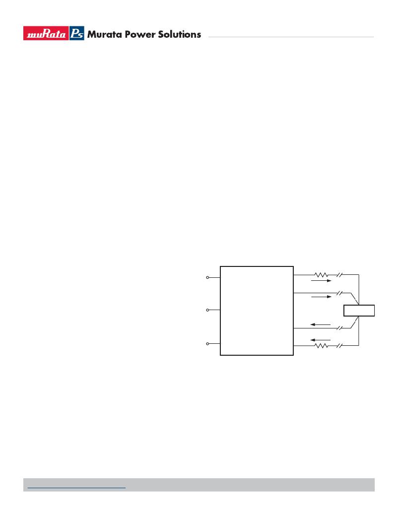
�Remote� Sense�
�Note:� The� Sense� and� V� OUT� lines� are� internally� connected� through� low-value�
�resistors.� Nevertheless,� if� the� sense� function� is� not� used� for� remote� regulation�
�the� user� should� connect� the� +Sense� to� +V� OUT� and� –Sense� to� –V� OUT� at� the� DC/�
�DC� converter� pins.� ULS� series� converters� employ� a� sense� feature� to� provide�
�point� of� use� regulation,� thereby� overcoming� moderate� IR� drops� in� PCB� conduc-�
�tors� or� cabling.� The� remote� sense� lines� carry� very� little� current� and� therefore�
�require� minimal� cross-sectional-area� conductors.� The� sense� lines,� which� are�
�capacitively� coupled� to� their� respective� output� lines,� are� used� by� the� feedback�
�control-loop� to� regulate� the� output.� As� such,� they� are� not� low� impedance� points�
�and� must� be� treated� with� care� in� layouts� and� cabling.� Sense� lines� on� a� PCB�
�should� be� run� adjacent� to� dc� signals,� preferably� ground.�
�[V� OUT� (+)-V� OUT� (–)]� –� [Sense(+)-Sense(–)]� ?� 10%V� OUT�
�In� cables� and� discrete� wiring� applications,� twisted� pair� or� other� techniques�
�should� be� used.� Output� over-voltage� protection� is� monitored� at� the� output� volt-�
�age� pin,� not� the� Sense� pin.� Therefore,� excessive� voltage� differences� between�
�V� OUT� and� Sense� in� conjunction� with� trim� adjustment� of� the� output� voltage� can�
�cause� the� over-voltage� protection� circuitry� to� activate� (see� Performance� Speci-�
�?cations� for� over-voltage� limits).� Power� derating� is� based� on� maximum� output�
�current� and� voltage� at� the� converter’s� output� pins.� Use� of� trim� and� sense� func-�
�tions� can� cause� output� voltages� to� increase,� thereby� increasing� output� power�
�beyond� the� converter’s� speci?ed� rating,� or� cause� output� voltages� to� climb� into�
�the� output� over-voltage� region.� Therefore,� the� designer� must� ensure:�
�(V� OUT� at� pins)� x� (I� OUT� )� ?� rated� output� power�
�Contact� and� PCB� resistance�
�losses� due� to� IR� drops�
�Current� Limiting�
�As� soon� as� the� output� current� increases� to� approximately� 130%� of� its� rated�
�value,� the� DC/DC� converter� will� go� into� a� current-limiting� mode.� In� this� condi-�
�tion,� the� output� voltage� will� decrease� proportionately� with� increases� in� output�
�current,� thereby� maintaining� somewhat� constant� power� dissipation.� This� is�
�+VIN�
�ON/OFF�
�CONTROL�
�+VOUT�
�+SENSE�
�TRIM�
�I� OUT�
�Sense� Current�
�LOAD�
�commonly� referred� to� as� power� limiting.� Current� limit� inception� is� de?ned�
�as� the� point� at� which� the� full-power� output� voltage� falls� below� the� speci?ed�
�tolerance.� See� Performance/Functional� Speci?cations.� If� the� load� current,� being�
�–SENSE�
�Sense� Return�
�I� OUT� Return�
�drawn� from� the� converter,� is� signi?cant� enough,� the� unit� will� go� into� a� short�
�circuit� condition� as� described� below.�
�–VIN�
�–VOUT�
�Short� Circuit� Condition�
�When� a� converter� is� in� current-limit� mode,� the� output� voltage� will� drop� as� the�
�output� current� demand� increases.� If� the� output� voltage� drops� too� low,� the� mag-�
�netically� coupled� voltage� used� to� develop� primary� side� voltages� will� also� drop,�
�thereby� shutting� down� the� PWM� controller.� Following� a� time-out� period,� the�
�PWM� will� restart� causing� the� output� voltage� to� begin� ramping� to� their� appropri-�
�ate� value.� If� the� short-circuit� condition� persists,� another� shutdown� cycle� will� be�
�initiated.� This� on/off� cycling� is� referred� to� as� “hiccup”� mode.� The� hiccup� cycling�
�reduces� the� average� output� current,� thereby� preventing� internal� temperatures�
�from� rising� to� excessive� levels.� The� ULS� Series� is� capable� of� enduring� an� inde?-�
�nite� short� circuit� output� condition.�
�Contact� and� PCB� resistance�
�losses� due� to� IR� drops�
�Figure� 4.� Remote� Sense� Circuit� Con?guration�
�On/Off� Control�
�The� input-side,� remote� On/Off� Control� function� can� be� ordered� to� operate� with�
�either� logic� type:�
�Positive� ("P"� suf?x)� logic� models� are� enabled� when� the� on/off� pin� is� left�
�open� (or� is� pulled� high,� applying� +3.5V� to� +15V� with� respect� to� –Input)� as� per�
�Figure� 5.� Positive-logic� devices� are� disabled� when� the� on/off� pin� is� pulled� low�
�(0� to� 1V� with� respect� to� –Input).�
�Negative� (“N”� suf?x)� logic� devices� are� off� when� pin� is� left� open� (or� pulled�
�high,� applying� +2.5V� to� +15V),� and� on� when� pin� is� pulled� low� (–0.1� to� +0.8V)�
�with� respect� to� –Input� as� shown� in� Figure� 5.�
�www.murata-ps.com/support�
�MDC_ULS� Series.B31� Page� 21� of� 24�
�相关PDF资料 |
PDF描述 |
|---|---|
| ULS-3.3/20-D48PH-C | CONVERT DC/DC 3.3V @ 20A POS CC |
| OSTTJ1131520 | CONN TERM BLK PLUG 11POS 3.81MM |
| OSTVL227151 | CONN TERM BLK HEADER 22POS 5MM |
| OSTVL227150 | CONN TERM BLK HEADER 22POS 5MM |
| OSTVL225150 | CONN TERM BLK HDR 22POS 5.08MM |
相关代理商/技术参数 |
参数描述 |
|---|---|
| ULS12P | 制造商:Electrolube 功能描述:PEN, ULTRASOLVE, 12ML |
| ULS-15/2-D48N-C | 功能描述:DC/DC转换器 30W 48Vin 15Vout 2A Neg Polarity TH RoHS:否 制造商:Murata 产品: 输出功率: 输入电压范围:3.6 V to 5.5 V 输入电压(标称): 输出端数量:1 输出电压(通道 1):3.3 V 输出电流(通道 1):600 mA 输出电压(通道 2): 输出电流(通道 2): 安装风格:SMD/SMT 封装 / 箱体尺寸: |
| ULS-15/2-D48NM-C | 功能描述:DC/DC转换器 30W 48Vin 15Vout 2A Neg Polarity SMT RoHS:否 制造商:Murata 产品: 输出功率: 输入电压范围:3.6 V to 5.5 V 输入电压(标称): 输出端数量:1 输出电压(通道 1):3.3 V 输出电流(通道 1):600 mA 输出电压(通道 2): 输出电流(通道 2): 安装风格:SMD/SMT 封装 / 箱体尺寸: |
| ULS-15/2-D48P-C | 功能描述:DC/DC转换器 30W 48Vin 15Vout 2A Pos Polarity TH RoHS:否 制造商:Murata 产品: 输出功率: 输入电压范围:3.6 V to 5.5 V 输入电压(标称): 输出端数量:1 输出电压(通道 1):3.3 V 输出电流(通道 1):600 mA 输出电压(通道 2): 输出电流(通道 2): 安装风格:SMD/SMT 封装 / 箱体尺寸: |
| ULS-15/2-D48PM-C | 功能描述:DC/DC转换器 30W 48Vin 15Vout 2A Pos Polarity SMT RoHS:否 制造商:Murata 产品: 输出功率: 输入电压范围:3.6 V to 5.5 V 输入电压(标称): 输出端数量:1 输出电压(通道 1):3.3 V 输出电流(通道 1):600 mA 输出电压(通道 2): 输出电流(通道 2): 安装风格:SMD/SMT 封装 / 箱体尺寸: |
发布紧急采购,3分钟左右您将得到回复。