- 您现在的位置:买卖IC网 > PDF目录297648 > UVQ-18/5.6-D24NB-C (MURATA POWER SOLUTIONS INC) DC-DC REG PWR SUPPLY MODULE PDF资料下载
参数资料
| 型号: | UVQ-18/5.6-D24NB-C |
| 厂商: | MURATA POWER SOLUTIONS INC |
| 元件分类: | 电源模块 |
| 英文描述: | DC-DC REG PWR SUPPLY MODULE |
| 封装: | ROHS COMPLIANT PACKAGE-8 |
| 文件页数: | 3/25页 |
| 文件大小: | 3470K |
| 代理商: | UVQ-18/5.6-D24NB-C |
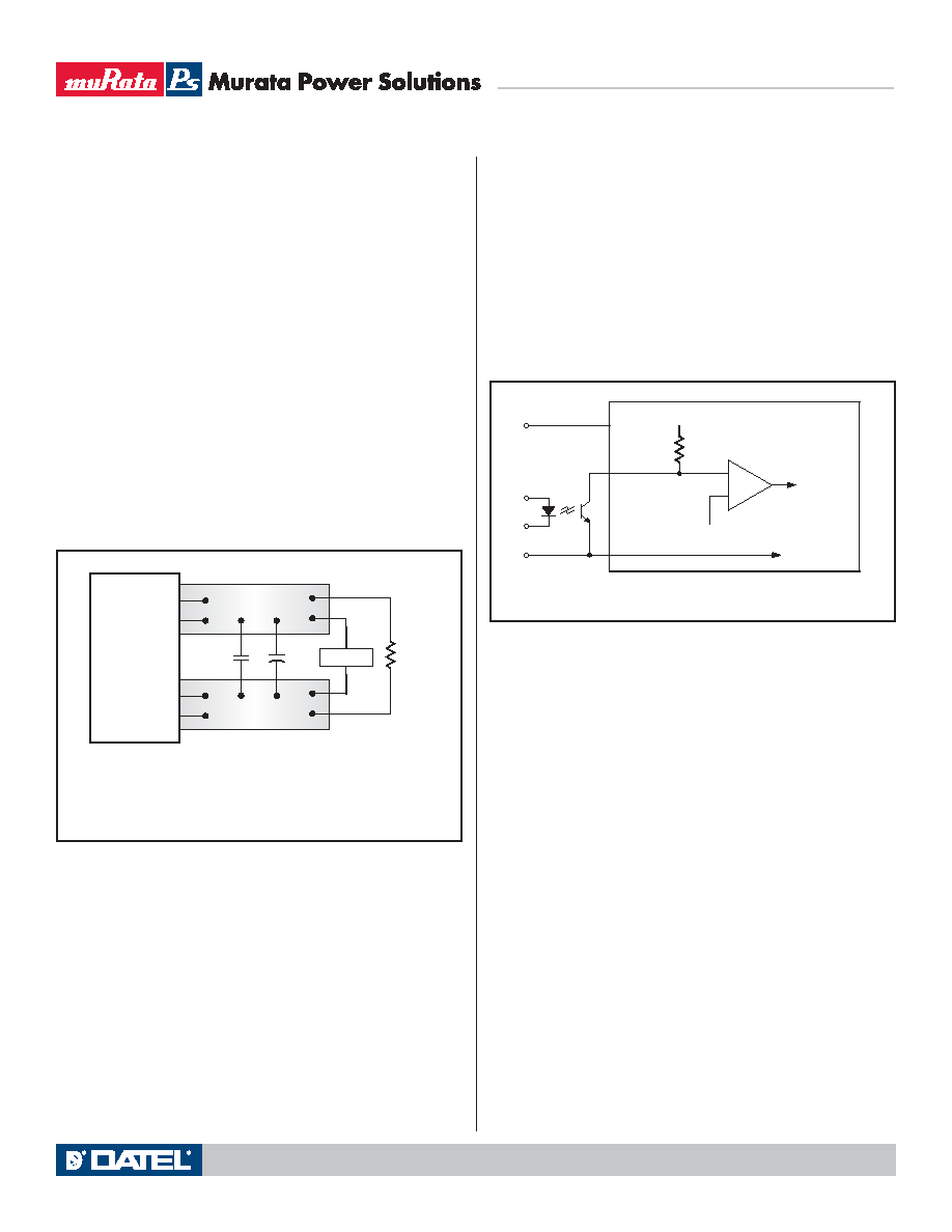
Figure 3. Measuring Output Ripple/Noise (PARD)
C1
C1 = 1F CERAMIC
C2 = 10F TANTALUM
LOAD 2-3 INCHES (51-76mm) FROM MODULE
C2
RLOAD
7
8
COPPER STRIP
4
5
COPPER STRIP
SCOPE
+OUTPUT
–OUTPUT
+SENSE
–SENSE
In critical applications, output ripple/noise (also referred to as periodic and
random deviations or PARD) can be reduced below specified limits using filter-
ing techniques, the simplest of which is the installation of additional external
output capacitors. Output capacitors function as true filter elements and
should be selected for bulk capacitance, low ESR, and appropriate frequency
response. In Figure 3, the two copper strips simulate real-world pcb imped-
ances between the power supply and its load. Scope measurements should be
made using BNC connectors or the probe ground should be less than inch
and soldered directly to the fixture.
All external capacitors should have appropriate voltage ratings and be
located as close to the converter as possible. Temperature variations for all
relevant parameters should be taken into consideration. OS-CONTM organic
semiconductor capacitors (www.sanyo.com) can be especially effective for
further reduction of ripple/noise.
The most effective combination of external I/O capacitors will be a function
of line voltage and source impedance, as well as particular load and layout
conditions. Our Applications Engineers can recommend potential solutions and
discuss the possibility of our modifying a given device’s internal filtering to
meet your specific requirements. Contact our Applications Engineering Group
for additional details.
Start-Up Threshold and Undervoltage Shutdown
Under normal start-up conditions, the UVQ Series will not begin to regulate
properly until the ramping input voltage exceeds the Start-Up Threshold.
Once operating, devices will turn off when the applied voltage drops below
the Undervoltage Shutdown point. Devices will remain off as long as the
undervoltage condition continues. Units will automatically re-start when the
applied voltage is brought back above the Start-Up Threshold. The hysteresis
built into this function avoids an indeterminate on/off condition at a single input
voltage. See Performance/Functional Specifications table for actual limits.
Start-Up Time
The VIN to VOUT Start-Up Time is the interval between the point at which a
ramping input voltage crosses the Start-Up Threshold voltage and the point at
which the fully loaded output voltage enters and remains within its specified
±1% accuracy band. Actual measured times will vary with input source imped-
ance, external input capacitance, and the slew rate and final value of the input
voltage as it appears to the converter. The On/Off to VOUT start-up time assumes
that the converter is turned off via the Remote On/Off Control with the nominal
input voltage already applied.
On/Off Control
The primary-side, Remote On/Off Control function (pin 2) can be specified
to operate with either positive or negative polarity. Positive-polarity devices
("P" suffix) are enabled when pin 2 is left open or is pulled high. Positive-
polarity devices are disabled when pin 2 is pulled low (0-0.8V with respect to
–Input). Negative-polarity devices are off when pin 2 is high/open and on when
pin 2 is pulled low. See Figure 4.
Dynamic control of the remote on/off function is best accomplished with a
mechanical relay or an open-collector/open-drain drive circuit (optically iso-
lated if appropriate). The drive circuit should be able to sink appropriate current
(see Performance Specifications) when activated and withstand appropriate
voltage when deactivated.
Current Limiting
When power demands from the output falls within the current limit inception
range for the rated output current, the DC/DC converter will go into a current
limiting mode. In this condition the output voltage will decrease proportionately
with increases in output current, thereby maintaining a somewhat constant
power dissipation. This is commonly referred to as power limiting. Current
limit inception is defined as the point where the full-power output voltage
falls below the specified tolerance. If the load current being drawn from the
converter is significant enough, the unit will go into a short circuit condition.
See “Short Circuit Condition.”
Short Circuit Condition
When a converter is in current limit mode the output voltages will drop as
the output current demand increases. If the output voltage drops too low, the
magnetically coupled voltage used to develop primary side voltages will also
drop, thereby shutting down the PWM controller. Following a time-out period
of about 50 milliseconds, the PWM will restart, causing the output voltages to
begin ramping to their appropriate values. If the short-circuit condition persists,
another shutdown cycle will be initiated. This on/off cycling is referred to as
“hiccup” mode. The hiccup cycling reduces the average output current, thereby
preventing internal temperatures from rising to excessive levels. The UVQ is
capable of enduring an indefinite short circuit output condition.
Figure 4. Driving the Remote On/Off Control Pin
MDC_UVQ Models.B04 Page 11 of 25
UVQ Series
Low Profile, Isolated Quarter Brick
2.5–40 Amp DC/DC Converters
Technical enquiries email: sales@murata-ps.com, tel: +1 508 339 3000
www.murata-ps.com
相关PDF资料 |
PDF描述 |
|---|---|
| UVQ-24/4.5-D48PBL2-C | DC-DC REG PWR SUPPLY MODULE |
| UZNBG2000X10 | SPECIALTY ANALOG CIRCUIT, PDSO10 |
| UZVP4525GTC | 265 mA, 250 V, P-CHANNEL, Si, SMALL SIGNAL, MOSFET |
| UZXM64N035L3 | 13 A, 35 V, 0.07 ohm, N-CHANNEL, Si, POWER, MOSFET, TO-220AB |
| UZXM64P035L3 | 12 A, 35 V, 0.105 ohm, P-CHANNEL, Si, POWER, MOSFET, TO-220AB |
相关代理商/技术参数 |
参数描述 |
|---|---|
| UVQ-2.5/35-D24N | 制造商:Murata Power Solutions 功能描述:Module DC-DC 1-OUT 2.5V 35A 87.5W 8-Pin Quarter-Brick |
| UVQ-2.5/35-D24NB-C | 功能描述:DC/DC转换器 87.5W 24V - 2.5V 35A NEG POL BASEPLATE RoHS:否 制造商:Murata 产品: 输出功率: 输入电压范围:3.6 V to 5.5 V 输入电压(标称): 输出端数量:1 输出电压(通道 1):3.3 V 输出电流(通道 1):600 mA 输出电压(通道 2): 输出电流(通道 2): 安装风格:SMD/SMT 封装 / 箱体尺寸: |
| UVQ-2.5/35-D24N-C | 功能描述:DC/DC转换器 87.5W 24V - 2.5V 35A NEGATIVE POLARITY RoHS:否 制造商:Murata 产品: 输出功率: 输入电压范围:3.6 V to 5.5 V 输入电压(标称): 输出端数量:1 输出电压(通道 1):3.3 V 输出电流(通道 1):600 mA 输出电压(通道 2): 输出电流(通道 2): 安装风格:SMD/SMT 封装 / 箱体尺寸: |
| UVQ-2.5/35-D24P | 制造商:Murata Power Solutions 功能描述:Module DC-DC 1-OUT 2.5V 35A 87.5W 8-Pin Quarter-Brick |
| UVQ-2.5/35-D24PB-C | 功能描述:DC/DC转换器 87.5W 24V - 2.5V 35A POS POL BASEPLATE RoHS:否 制造商:Murata 产品: 输出功率: 输入电压范围:3.6 V to 5.5 V 输入电压(标称): 输出端数量:1 输出电压(通道 1):3.3 V 输出电流(通道 1):600 mA 输出电压(通道 2): 输出电流(通道 2): 安装风格:SMD/SMT 封装 / 箱体尺寸: |
发布紧急采购,3分钟左右您将得到回复。