- 您现在的位置:买卖IC网 > PDF目录13541 > UWF0J330MCL1GB (Nichicon)CAP ALUM 33UF 6.3V 20% SMD PDF资料下载
参数资料
| 型号: | UWF0J330MCL1GB |
| 厂商: | Nichicon |
| 文件页数: | 1/1页 |
| 文件大小: | 0K |
| 描述: | CAP ALUM 33UF 6.3V 20% SMD |
| 标准包装: | 1,000 |
| 系列: | WF |
| 电容: | 33µF |
| 额定电压: | 6.3V |
| 容差: | ±20% |
| 寿命@温度: | 105°C 时为 1000 小时 |
| 工作温度: | -55°C ~ 105°C |
| 特点: | 通用 |
| 纹波电流: | 80mA |
| 阻抗: | 2.6 欧姆 |
| 安装类型: | 表面贴装 |
| 封装/外壳: | 径向,Can - SMD |
| 尺寸/尺寸: | 0.197" 直径(5.00mm) |
| 高度 - 座高(最大): | 0.217"(5.50mm) |
| 表面贴装占地面积: | 0.209" L x 0.209" W(5.30mm x 5.30mm) |
| 包装: | 带卷 (TR) |
�� �
�
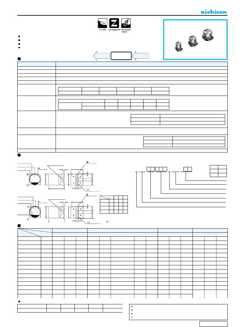
�ALUMINUM� ELECTROLYTIC� CAPACITORS�
�WF�
�Chip� Type,� Low� Impedance�
�series�
�Chip� type,� low� impedance� temperature� range� up� to� +105� °� C� .�
�Designed� for� surface� mounting� on� high� density� PC� board.�
�Applicable� to� automatic� mounting� machine� fed� with� carrier� tape.�
�Compliant� to� the� RoHS� directive� (2011/65/EU).�
�Specifications�
�WG�
�Low�
�Impedance�
�WF�
�Low�
�Impedance�
�WT�
�Item�
�Category� Temperature� Range�
�Rated� Voltage� Range�
�Rated� Capacitance� Range�
�Capacitance� Tolerance�
�Leakage� Current�
�Performance� Characteristics�
�–� 55� to� +105� °� C�
�6.3� to� 35V�
�1� to� 220μF�
�±� 20%� at� 120Hz,� 20� °� C�
�After� 2� minutes'� application� of� rated� voltage,� leakage� current� is� not� more� than� 0.01CV� or� 3� (μA)� ,� whichever� is� greater.�
�Measurement� frequency� :� 120Hz� at� 20� °� C�
�Tangent� of� loss� angle� (tan� δ� )�
�Rated� voltage� (V)�
�tan� δ� (� MAX.� )�
�6.3�
�0.22�
�10�
�0.19�
�16�
�0.16�
�25�
�0.14�
�35�
�0.12�
�Measurement� frequency� :� 120Hz�
�Stability� at� Low� Temperature�
�Rated� voltage� (V)�
�Impedance� ratio� Z� –� 25� °� C� /� Z+20� °� C�
�6.3�
�2�
�10�
�2�
�16�
�2�
�25�
�2�
�35�
�2�
�ZT� /� Z20� (MAX.)�
�Z� –� 55� °� C� /� Z+20� °� C�
�4�
�4�
�3�
�3�
�3�
�The� specifications� listed� at� right� shall� be� met� when�
�Capacitance� change�
�Within� ±20%� of� the� initial� capacitance� value�
�Endurance�
�the� capacitors� are� restored� to� 20� °� C� after� the� rated�
�voltage� is� applied� for� 1000� hours� at� 105� °� C.�
�tan� δ�
�Leakage� current�
�200%� or� less� than� the� initial� specified� value�
�Less� than� or� equal� to� the� initial� specified� value�
�Shelf� Life�
�After� storing� the� capacitors� under� no� load� at� 105� °� C� for� 1000� hours� and� then� performing� voltage� treatment� based� on� JIS� C� 5101-4� clause� 4.1� at�
�20� °� C,� they� shall� meet� the� specified� values� for� the� endurance� characteristics� listed� above.�
�Resistance� to� soldering�
�heat�
�The� capacitors� are� kept� on� a� hot� plate� for� 30� seconds,� which� is�
�maintained� at� 250� °� C.� The� capacitors� shall� meet� the�
�characteristic� requirements� listed� at� right� when� they� are� removed�
�from� the� plate� and� restored� to� 20� °� C.�
�Capacitance� change�
�tan� δ�
�Leakage� current�
�Within� ±10%� of� the� initial� capacitance� value�
�Less� than� or� equal� to� the� initial� specified� value�
�Less� than� or� equal� to� the� initial� specified� value�
�Marking�
�Chip� Type�
�(� φ� 4� to� φ� 6.3)�
�Black� print� on� the� case� top.�
�Type� numbering� system� (Example� :� 16V� 10� μ� F)�
�105� ?� C� Marking�
�Capacitance�
�Lot� No.�
�Plastic� platform�
�Voltage� 0.3� MAX.�
�C� ±� 0.2�
�Positive�
�1� 2� 3� 4� 5� 6� 7� 8� 9� 10� 11� 12� 13� 14�
�U� W� F� 1� C� 1� 0� 0� M� C� L� 1� G� B�
�φ� D�
�4� to� 6.3�
�Code�
�GB�
�8�
�GS�
�Taping� code�
�Configuration�
�5.4�
�(� φ� 8)�
�105� ?� C� Marking�
�Capacitance�
�Trade� mark�
�Voltage�
�+0.1�
�-0.2�
�Plastic� platform�
�0.3� MAX.�
�0.5� to� 0.8�
�C� ±� 0.2�
�Negative�
�Positive�
�A�
�B�
�φ� D�
�4�
�1.8�
�4.3�
�5�
�2.1�
�5.3�
�(mm)�
�6.3� 8�
�2.4� 3.3�
�6.6� 8.3�
�Capacitance� tolerance� (� ±� 20%)�
�Rated� capacitance� (10� μ� F)�
�Rated� voltage� (16V)�
�Series� name�
�Type�
�C�
�4.3�
�5.3�
�6.6�
�8.3�
�Lot� No.�
�E�
�1.0�
�1.3�
�2.2�
�2.3�
�Dimensions�
�6.2� ±� 0.3�
�0.5� to� 0.8�
�Negative�
�Voltage� mark� for� 6.3V� is� 6V.�
�V�
�6.3�
�10�
�16�
�25�
�35�
�Cap.� (μF)�
�1�
�1.5�
�2.2�
�3.3�
�Code�
�010�
�1R5�
�2R2�
�3R3�
�0J�
�1A�
�1C�
�1E�
�4�
�4�
�4�
�4�
�1V�
�5.0�
�5.0�
�5.0�
�5.0�
�50�
�50�
�50�
�50�
�4.7�
�6.8�
�4R7�
�6R8�
�4�
�4�
�5.0�
�5.0�
�50�
�50�
�4�
�5�
�5.0�
�2.6�
�50�
�80�
�10�
�15�
�100�
�150�
�4�
�5�
�5.0�
�2.6�
�50�
�80�
�5�
�6.3�
�2.6�
�1.3�
�80�
�115�
�5�
�6.3�
�2.6�
�1.3�
�80�
�115�
�22�
�33�
�47�
�220�
�330�
�470�
�4�
�5�
�5�
�5.0�
�2.6�
�2.6�
�50�
�80�
�80�
�5�
�5�
�6.3�
�2.6�
�2.6�
�1.3�
�80�
�80�
�115�
�5�
�6.3�
�6.3�
�2.6�
�1.3�
�1.3�
�80�
�115�
�115�
�6.3�
�6.3�
�8�
�1.3�
�1.3�
�0.8�
�115�
�115�
�150�
�6.3�
�8�
�8�
�1.3�
�0.8�
�0.8�
�115�
�150�
�150�
�68�
�680�
�6.3�
�1.3�
�115�
�6.3�
�1.3�
�115�
�8�
�0.8�
�150�
�8�
�0.8�
�150�
�Impedance� Rated�
�100�
�150�
�220�
�101�
�151�
�221�
�6.3�
�8�
�8�
�1.3�
�0.8�
�0.8�
�115�
�150�
�150�
�8�
�8�
�0.8�
�0.8�
�150�
�150�
�8�
�0.8�
�150�
�Case� size�
�φ� D� (mm)�
�ripple�
�Frequency� coefficient� of� rated� ripple� current�
�Max.� Impedance� (� ?� )� at� 20� °� C� 100kHz�
�Rated� ripple� current� (mArms)� at� 105� °� C� 100kHz�
�Frequency�
�Coefficient�
�50� Hz�
�0.35�
�120� Hz�
�0.50�
�300� Hz�
�0.64�
�1� kHz�
�0.83�
�10� kHz� or� more�
�1.00�
�Taping� specifications� are� given� in� page� 23.�
�Recommended� land� size,� soldering� by� reflow� are� given� in� page� 18,� 19.�
�Please� select� UJ(p.164)� series� if� high� C/V� products� are� reqired.�
�Please� refer� to� page� 3� for� the� minimum� order� quantity.�
�CAT.8100C�
�相关PDF资料 |
PDF描述 |
|---|---|
| VE-J6P-EX-F1 | CONVERTER MOD DC/DC 13.8V 75W |
| VE-J6N-EX-F4 | CONVERTER MOD DC/DC 18.5V 75W |
| UUT1A470MCL1GS | CAP ALUM 47UF 10V 20% SMD |
| UUT0G101MCL1GS | CAP ALUM 100UF 4V 20% SMD |
| VE-J6N-EX-F3 | CONVERTER MOD DC/DC 18.5V 75W |
相关代理商/技术参数 |
参数描述 |
|---|---|
| UWF0J470MCL | 制造商:NICHICON 制造商全称:Nichicon corporation 功能描述:ALUMINUM ELECTROLYTIC CAPACITORS |
| UWF0J470MCL1GB | 功能描述:铝质电解电容器-SMD 6.3volts 47uF 105c 5X5.4 RoHS:否 制造商:Vishay/BC Components 电容:2200 uF 容差:20 % 电压额定值:16 V ESR: 工作温度范围:- 55 C to + 150 C 尺寸:16 mm W x 16 mm L x 21 mm H 产品:High Temp Electrolytic Capacitors |
| UWF0J680MCL | 制造商:NICHICON 制造商全称:Nichicon corporation 功能描述:ALUMINUM ELECTROLYTIC CAPACITORS |
| UWF0J680MCL1GB | 功能描述:铝质电解电容器-SMD 6.3volts 68uF 105c 6.3X5.4 RoHS:否 制造商:Vishay/BC Components 电容:2200 uF 容差:20 % 电压额定值:16 V ESR: 工作温度范围:- 55 C to + 150 C 尺寸:16 mm W x 16 mm L x 21 mm H 产品:High Temp Electrolytic Capacitors |
| UWF1A101MBR1GS | 功能描述:铝质电解电容器-SMD RoHS:否 制造商:Vishay/BC Components 电容:2200 uF 容差:20 % 电压额定值:16 V ESR: 工作温度范围:- 55 C to + 150 C 尺寸:16 mm W x 16 mm L x 21 mm H 产品:High Temp Electrolytic Capacitors |
发布紧急采购,3分钟左右您将得到回复。