- 您现在的位置:买卖IC网 > PDF目录276629 > V048F160T015 1-OUTPUT DC-DC REG PWR SUPPLY MODULE PDF资料下载
参数资料
| 型号: | V048F160T015 |
| 元件分类: | 电源模块 |
| 英文描述: | 1-OUTPUT DC-DC REG PWR SUPPLY MODULE |
| 封装: | ROHS COMPLIANT PACKAGE-9 |
| 文件页数: | 1/14页 |
| 文件大小: | 1650K |
| 代理商: | V048F160T015 |
vicorpower.com
800-735-6200
VI Chip Regulator
P048F048T24AL
Rev. 3.7
Page 1 of 14
48 V input VI Chip
TM PRM
Vin range 36 – 75 Vdc
High density – 813 W/in3
Small footprint – 215 W/in
2
Low weight – 0.5 oz (15 g)
Adaptive Loop feedback
ZVS buck-boost regulator
1.45 MHz switching frequency
96% Efficiency
125C operation (Tj)
P048F048T24AL
P048F048M24AL
Vin = 36 – 75 V
Vf = 26 – 55 V
Pf = 240 W
If = 5 A
PRMTM
Regulator
Product Description
The VI Chip regulator is a very efficient non-isolated
regulator capable of both boosting and bucking a wide range
input voltage. It is specifically designed to provide a controlled
Factorized Bus distribution voltage for powering downstream
VTMTM Transformer — fast, efficient, isolated, low noise
Point-of-Load (POL) converters. In combination, PRMs and
VTMsTM form a complete DC-DC converter subsystem
offering all of the unique benefits of Vicor’s Factorized Power
ArchitectureTM (FPA)TM: high density and efficiency; low noise
operation; architectural flexibility; extremely fast transient
response; and elimination of bulk capacitance at the Point-of-
Load (POL).
In FPA systems, the POL voltage is the product of the
Factorized Bus voltage delivered by the PRM and the
"K-factor" (the fixed voltage transformation ratio) of a
downstream VTM. The PRM controls the Factorized Bus
voltage to provide regulation at the POL. Because VTMs
perform true voltage division and current multiplication,
the Factorized Bus voltage may be set to a value that is
substantially higher than the bus voltages typically found in
"intermediate bus" systems, reducing distribution losses and
enabling use of narrower distribution bus traces. A PRM-VTM
chip set can provide up to 100 A or 230 W at a FPA system
density of 169 A/in3 or 390 W/in3 — and because the PRM
can be located, or "factorized," remotely from the POL, these
power densities can be effectively doubled.
The PRM described in this data sheet features a unique
"Adaptive Loop" compensation feedback: a single wire
alternative to traditional remote sensing and feedback loops
that enables precise control of an isolated POL voltage
without the need for either a direct connection to the load
or for noise sensitive, bandwidth limiting, isolation devices
in the feedback path.
Parameter
Values
Unit
Notes
+In to -In
-1.0 to 85.0
Vdc
PC to -In
-0.3 to 6.0
Vdc
PR to -In
-0.3 to 9.0
Vdc
IL to -In
-0.3 to 6.0
Vdc
VC to -In
-0.3 to 18.0
Vdc
+Out to -Out
-0.3 to 59
Vdc
SC to -Out
-0.3 to 3.0
Vdc
VH to -Out
-0.3 to 9.5
Vdc
OS to -Out
-0.3 to 9.0
Vdc
CD to -Out
-0.3 to 9.0
Vdc
SG to -Out
100
mA
Continuous output current
5
Adc
Continuous output power
240
W
Case temperature during reflow
225
°C
MSL 5
245
°C
MSL 6
Operating junction temperature
-55 to 125
°C
M-Grade
-40 to 125
°C
T-Grade
Storage temperature
-65 to 125
°C
M-Grade
-40 to 125
°C
T-Grade
+Out
–Out
+In
–In
VC
PC
TM
IL
VH
PR
NC
SG
SC
PRM-AL
OS
NC
CD
L
O
A
D
Factorized
Bus (Vf)
Vin
ROS
RCD
– In
PC
VC
TM
+In
– Out
+Out
VTM
– Out
+Out
K
Ro
0.01
μF
0.4
μH
10 Ω
10 kΩ
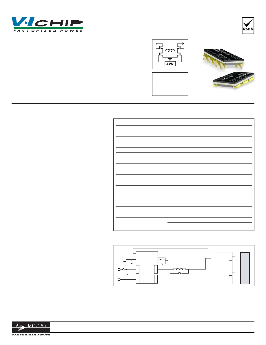
DC-DC Converter
Absolute Maximum Ratings
P048F048T24AL is used with 048 input series VTM to provide a regulated & isolated output.
相关PDF资料 |
PDF描述 |
|---|---|
| V048F060T040 | 1-OUTPUT DC-DC REG PWR SUPPLY MODULE |
| VI-B0Z-MX | 1-OUTPUT DC-DC BOOSTER MODULE |
| VI-B10-CV | 1-OUTPUT 150 W DC-DC BOOSTER MODULE |
| VI-B43-IU | 1-OUTPUT 200 W DC-DC BOOSTER MODULE |
| VI-210-EY-F3 | 1-OUTPUT 50 W DC-DC REG PWR SUPPLY MODULE |
相关代理商/技术参数 |
参数描述 |
|---|---|
| V048F160T015-CB | 功能描述:VTM CURRENT MULTIPLIER EVAL BOAR RoHS:是 类别:编程器,开发系统 >> 评估板 - DC/DC 与 AC/DC(离线)SMPS 系列:V-I Chip™, VTM™ 产品培训模块:Obsolescence Mitigation Program 标准包装:1 系列:True Shutdown™ 主要目的:DC/DC,步升 输出及类型:1,非隔离 功率 - 输出:- 输出电压:- 电流 - 输出:1A 输入电压:2.5 V ~ 5.5 V 稳压器拓扑结构:升压 频率 - 开关:3MHz 板类型:完全填充 已供物品:板 已用 IC / 零件:MAX8969 |
| V048F160T019 | 制造商:VICOR 制造商全称:Vicor Corporation 功能描述:VI Chip - PRM-AL Pre-Regulator Module |
| V048F160T025 | 制造商:POWERBOX 制造商全称:Powerbox 功能描述:300W DC/DC VOLTAGE TRANSFORMATION MODULE PRELIMINARY |
| V048F160T030 | 制造商:POWERBOX 制造商全称:Powerbox 功能描述:300W DC/DC VOLTAGE TRANSFORMATION MODULE PRELIMINARY |
| V048F160T040 | 制造商:POWERBOX 制造商全称:Powerbox 功能描述:300W DC/DC VOLTAGE TRANSFORMATION MODULE PRELIMINARY |
发布紧急采购,3分钟左右您将得到回复。