- 您现在的位置:买卖IC网 > PDF目录361766 > W156 Clocks and Buffers PDF资料下载
参数资料
| 型号: | W156 |
| 英文描述: | Clocks and Buffers |
| 中文描述: | 时钟和缓冲器 |
| 文件页数: | 9/13页 |
| 文件大小: | 167K |
| 代理商: | W156 |
W158
Document #: 38-07164 Rev. *A
Page 9 of 13
Note:
37. PCI clock is CPU/4 for CPU = 133 MHz and CPU/3 for CPU = 100 MHz.
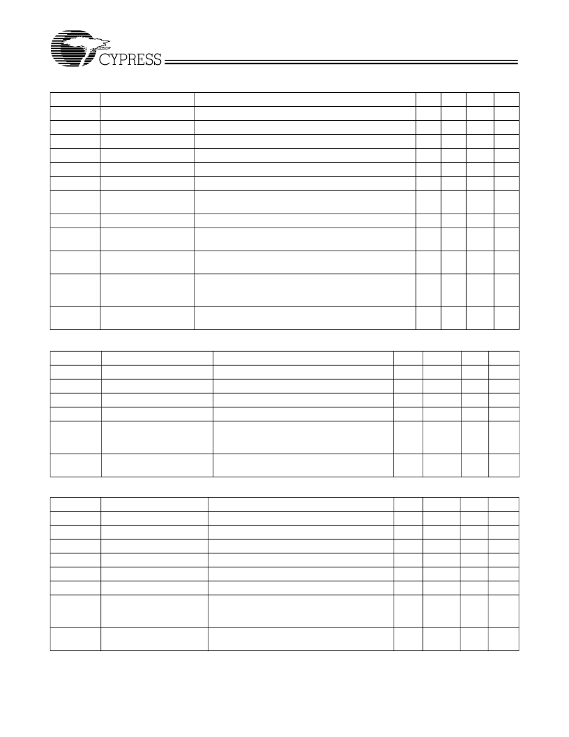
PCI Clock Outputs, PCI_F and PCI1:7 (Lump Capacitance Test Load = 30 pF)
Parameter
Description
t
P
Period
t
H
High Time
Duration of clock cycle above 2.4V
t
L
Low Time
Duration of clock cycle below 0.4V
t
R
Output Rise Edge Rate
Measured from 0.4V to 2.4V
t
F
Output Fall Edge Rate
Measured from 2.4V to 0.4V
t
D
Duty Cycle
Measured on rising and falling edge at 1.5V
t
JC
Jitter, Cycle-to-Cycle
Measured on rising edge at 1.5V. Maximum difference of
cycle time between two adjacent cycles.
t
SK
Output Skew
Measured on rising edge at 1.5V
t
O
3V66 to PCI Clock
Skew
1.5V. 3V66 leads PCI output.
t
q
CPU to PCI Clock Skew Covers all CPU/PCI outputs. Measured on rising edge at
1.5V. CPU leads PCI output.
f
ST
Frequency Stabilization
from Power-up (cold
start)
Z
o
AC Output Impedance
Average value during switching transition. Used for deter-
mining series termination value.
Test Condition/Comments
Min.
30
12
12
1
1
45
Typ.
Max.
Unit
ns
ns
ns
V/ns
V/ns
%
ps
Measured on rising edge at 1.5V
[37]
4
4
55
500
500
3
ps
ns
Covers all 3V66/PCI outputs. Measured on rising edge at
1.5
1.5
4
ns
Assumes full supply voltage reached within 1 ms from
power-up. Short cycles exist prior to frequency stabilization.
3
ms
15
REF Clock Outputs, REF0:1 (Lump Capacitance Test Load = 20 pF)
Parameter
Description
f
Frequency, Actual
t
R
Output Rise Edge Rate
t
F
Output Fall Edge Rate
t
D
Duty Cycle
f
ST
Frequency Stabilization from
Power-up (cold start)
Test Condition/Comments
Frequency generated by crystal oscillator
Measured from 0.4V to 2.4V
Measured from 2.4V to 0.4V
Measured on rising and falling edge at 1.5V
Assumes full supply voltage reached within
1 ms from power-up. Short cycles exist prior to
frequency stabilization.
Average value during switching transition. Used
for determining series termination value.
Min.
Typ.
14.318
Max.
Unit
MHz
V/ns
V/ns
%
ms
0.5
0.5
45
2
2
55
3
Z
o
AC Output Impedance
25
48-MHZ Clock Output (Lump Capacitance Test Load = 20 pF)
Parameter
Description
f
Frequency, Actual
f
D
Deviation from 48 MHz
m/n
PLL Ratio
t
R
Output Rise Edge Rate
t
F
Output Fall Edge Rate
t
D
Duty Cycle
f
ST
Frequency Stabilization
from Power-up (cold start)
Test Condition/Comments
Determined by PLL divider ratio (see m/n below)
(48.008
–
48)/48
(14.31818 MHz x 57/17 = 48.008 MHz)
Measured from 0.4V to 2.4V
Measured from 2.4V to 0.4V
Measured on rising and falling edge at 1.5V
Assumes full supply voltage reached within 1 ms
from power-up. Short cycles exist prior to fre-
quency stabilization.
Average value during switching transition. Used
for determining series termination value.
Min.
Typ.
48.008
+167
57/17
Max.
Unit
MHz
ppm
0.5
0.5
45
2
2
V/ns
V/ns
%
ms
55
3
Z
o
AC Output Impedance
25
相关PDF资料 |
PDF描述 |
|---|---|
| W158H | CPU System Clock Generator |
| W159BH | CPU SYSTEM CLOCK GENERATOR|CMOS|SSOP|56PIN|PLASTIC |
| W159H | CPU System Clock Generator |
| W15NB50 | N-CHANNEL 500V - 0.33ohm - 14.6A - T0-247/ISOWATT218 PowerMESH MOSFET |
| W15NK90Z | N-CHANNEL 900V-0.40ohm-15A TO-247 Zener-Protected SuperMESH MOSFET |
相关代理商/技术参数 |
参数描述 |
|---|---|
| W156220-2000-TB | 功能描述:CONN SOCKET 20POS 2MM SMD RoHS:否 类别:连接器,互连式 >> 矩形- 接头,插座,母插口 系列:1502 标准包装:37 系列:- 连接器类型:插座 触点类型::母形插口 位置数:16 加载位置的数目:全部 间距:0.079"(2.00mm) 行数:2 行间距:0.079"(2.00mm) 安装类型:表面贴装 端子:焊接 紧固型:- 特点:- 触点表面涂层:金 触点涂层厚度:15µin(0.38µm) 颜色:自然色 包装:散装 其它名称:SPE1033 |
| W156HT | 制造商:Rochester Electronics LLC 功能描述:- Bulk |
| W-1573 | 功能描述:螺丝和紧固件 NYLON WSHR KIT 25 PK RoHS:否 制造商:Unspecified 产品: 类型:Washer 螺纹大小: 长度: 材料:Steel 电镀:Nickel 螺丝头: 螺丝类型: |
| W1577 | 制造商:Performance Tool 功能描述:Mini Tool Set Combo with Ratcheting/Precision/ Screwdrivers and Bit Set 制造商:PERFORMANCE TOOLS 功能描述:MINI TOOL SET COMBO |
| W158 | 制造商:CYPRESS 制造商全称:Cypress Semiconductor 功能描述:Spread Spectrum System Frequency Synthesizer |
发布紧急采购,3分钟左右您将得到回复。